you still need a resistor, preferably adjustable, to trim the bias current.pheonix358 said:I want to add an extra thermaltrak each side. ...............The extra diode should obviate the need for a resister in this part of the circuit. ...........
Sc Uld2
"it might be even better to convert the mirror to a Wilson or Widlar type. But, add that extra resistor that is discussed in the mirrors thread."
Andrew.
It is only a small voltage drop required in most cases to achieve the balance. Using different mirror types will normally mean changing some values in either the emitter follower or the VAS.
I would also point out that my original observation from 1987 did not involve current mirrors. It was with a very well matched differential pair ,that was loaded by another closely matched differential pair (actually, a LM394H) The type of current mirror has nothing to do with the results achieved, except where it allows much closer balance of the LTP currents. The original finding of markedly improved soundstage and general performance, using a very well matched LTP, was when their currents were so close that, the difference in collector voltages was <5mV. This has been duplicated by other Sydney based members in their own designs, including the SC ULD2 being discussed.
Try simulating that finding !
Alex
Sorry to dig up a somewhat old thread, but I've just got one of these kits (after completing the Silicon Chip headphone amp, which has been a big success), and am trying to understand some of the suggestions above. I'm quite new to electronics, so if anyone would be so kind as to help me a little I'd really appreciate it! My questions are:
- Does the trim-pot mentioned by Alfred go just before Q12's collector? And the idea is to get 7-10mV across the 0.1Ohm resistors, right?
- After removing the 100R's from Q10 and Q11 emitters, I add back a 220R and 1uf cap in parallel, right? Where do these 2 components go? Also: what kind of cap, and what voltage?
- Regarding the suggestion: 'get rid of the 6.8k 1W(jumper), Q5 Re=300R, Q7 Re=100R'. Those resistors would be referring to the ones at the emitters, right? Should this tweak be in addition to the other 2 changes above?
By JP - Regarding the suggestion: 'get rid of the 6.8k 1W(jumper), Q5 Re=300R, Q7 Re=100R'. Those resistors would be referring to the ones at the emitters, right? Should this tweak be in addition to the other 2 changes above
It will work good as SC has it (with the 6.8k) I just stated
what doug self (circuits original designer) concluded.
Mine is the same , but has no 6.8k .. collector of the CCS
goes direct to the 2 LTP resistors.(don't do that on yours)
If you do decide to go the self type 2 route , I have found 1uFAfter removing the 100R's from Q10 and Q11 emitters, I add back a 220R and 1uf cap in parallel, right? Where do these 2 components go? Also: what kind of cap, and what voltage?
for the cap is too big ,I use a .02uf/63v for mine. It will work fine
as a type 1 (2-100R's , like it is). Your choice.Where to put the
220R +cap ? , between the Q10/11 emitters.
Have fun , it is a VERY reliable amp.
OS
Ultra LD 200W Amp.
I started this thread in DEC 08 when i built a pair of these amps , so heres my experiance so Far.
I am very satisfied with the performance of this amp, has been running with no problems since DEC, once i fixed the Bias problem with help from other members of this Thread & John Clark the Amps designer.
I ended up with a 20 Ohm 10Turn trim pot mounted on the board between the 2 100ohm resistors adjacent to Q10 & Q11 , cut the track between DQ13 & DQ14 & connected the Pot there. Works Fine, once set i have not had to readjust it at all.
You will find that the voltages across the 4 .1Ohm resistors will vary a little bit due to transistor variation , so i just set mine to a average value so all 4 are between 7-10Mv. (Matched transistor sets would help here)
The only other mods i made are as follows , Replaced the 47uf input cap with a Non Polar "Blackgate". ( May try a HQ film Cap later)
Replaced the 220Uf 16V feedback Cap with a "Blackgate"
also the 2 47Uf 35V caps with "Blackgates."
So far i have not found any reason to do any more mods as the Amp sounds great .
very,very quiet & stable.
I built mine with Seperate Power supplies, transformers Etc for each channel (Monoblocks) Used my own Power supplys not the Jaycar one.
I did wonder if the kit has been updated with a pot to fix the Bias problem.
Hope this is helpful.
jp_howard said:Sorry to dig up a somewhat old thread, but I've just got one of these kits (after completing the Silicon Chip headphone amp, which has been a big success), and am trying to understand some of the suggestions above. I'm quite new to electronics, so if anyone would be so kind as to help me a little I'd really appreciate it!
Has anyone got any more suggestions regarding this kit? For those who have completed it: have you been satisfied with the results?
I started this thread in DEC 08 when i built a pair of these amps , so heres my experiance so Far.
I am very satisfied with the performance of this amp, has been running with no problems since DEC, once i fixed the Bias problem with help from other members of this Thread & John Clark the Amps designer.
I ended up with a 20 Ohm 10Turn trim pot mounted on the board between the 2 100ohm resistors adjacent to Q10 & Q11 , cut the track between DQ13 & DQ14 & connected the Pot there. Works Fine, once set i have not had to readjust it at all.
You will find that the voltages across the 4 .1Ohm resistors will vary a little bit due to transistor variation , so i just set mine to a average value so all 4 are between 7-10Mv. (Matched transistor sets would help here)
The only other mods i made are as follows , Replaced the 47uf input cap with a Non Polar "Blackgate". ( May try a HQ film Cap later)
Replaced the 220Uf 16V feedback Cap with a "Blackgate"
also the 2 47Uf 35V caps with "Blackgates."
So far i have not found any reason to do any more mods as the Amp sounds great .
very,very quiet & stable.
I built mine with Seperate Power supplies, transformers Etc for each channel (Monoblocks) Used my own Power supplys not the Jaycar one.
I did wonder if the kit has been updated with a pot to fix the Bias problem.
Hope this is helpful.
Many thanks for those comments, OS and Micky. To answer your question - no the kit has not been updated with a pot (at least not the one I bought from Jaycar last week).
I'll report back to this forum with a 'beginners how-to' once I've got everything working, so that any n00bs like me who would like to try this kit can follow along with my mistakes and successes... (If any newbies are reading this, my initial reaction to this kit is that it's much much more complex than the headphone amp kit [which was my first project], because there's a much higher voltage to worry about, the trickiness of a double-sided board, and the challenge of mounting a big heavy heatsink. So don't make this your first project!)
I'll report back to this forum with a 'beginners how-to' once I've got everything working, so that any n00bs like me who would like to try this kit can follow along with my mistakes and successes... (If any newbies are reading this, my initial reaction to this kit is that it's much much more complex than the headphone amp kit [which was my first project], because there's a much higher voltage to worry about, the trickiness of a double-sided board, and the challenge of mounting a big heavy heatsink. So don't make this your first project!)
jp_howard said:Sorry to dig up a somewhat old thread, but I've just got one of these kits (after completing the Silicon Chip headphone amp, which has been a big success), and am trying to understand some of the suggestions above. I'm quite new to electronics, so if anyone would be so kind as to help me a little I'd really appreciate it! My questions are:Has anyone got any more suggestions regarding this kit? For those who have completed it: have you been satisfied with the results?
- Does the trim-pot mentioned by Alfred go just before Q12's collector? And the idea is to get 7-10mV across the 0.1Ohm resistors, right?
- After removing the 100R's from Q10 and Q11 emitters, I add back a 220R and 1uf cap in parallel, right? Where do these 2 components go? Also: what kind of cap, and what voltage?
- Regarding the suggestion: 'get rid of the 6.8k 1W(jumper), Q5 Re=300R, Q7 Re=100R'. Those resistors would be referring to the ones at the emitters, right? Should this tweak be in addition to the other 2 changes above?
SCULD POWER AMP MODS
It may be best to make the standard kit up then start modifying, this is get it working first.
The kit does not come with enough screws for the complete mounting, using a cast heat-sink you may need to invest in a 3mm tap and a 2.5 mm drill to thread holes, through holes a a little difficult with the suggested heat-sink.
A I have a rather extensive workshop with both sheet-metal and turning capacity I make most of my own boxes etc, but for those with limited resources seeking some help may be required or finding someone with the tools and even grater someone who will lend them to you. A challenge in deed.
A 100R trim pot is soldered to the top track (runs diagonally towards the 1000uf cap) on the board in front of Q13 collector after cutting the track and remove the solder mask for soldering, this allows setting the bias within the better 100ma Class AB setting, I measure across two 0.1R for a voltage of 20mv, this gives a reading to include variations in resistor values and two transistors in an active state with any variations in active transistor expectations taken into the equation. ( one person suggested that the value here could be as low as 7.6R)
Remove the two 100R emitter resistors on Q10 + Q11 replace with one 220R resistor and 1uf capacitor, the 1uf cap is a standard in this position and as OStripper points out you can tune the circuit to you liking. I drilled two holes in front of the transistors Q10/11, on the under side I bent the wires to join to the emitters of Q10/11 and piggy backed the cap on top of the resistor. If everything else is going well you can hear significant difference when this mod is accomplished.
The 6.8K resistor in the tail of the LTP was left as the philosophy for removing it did not enhance the sound and made the LTP run hotter.
The 0R link across the power rails was replaced by a 200R pot in line with mods suggested by SandyK, this is a significant before and after difference.
The 47R which sets the CCS value for the VAS is replaced with 100R, this runs cooler and the increased bias as suggested in the SC article for increasing the O/P bias current is not required if you put in the 100R pot or whatever value you desire, to increase the voltage reading across the 0.1R
The 100R next to it is increased to 150R to make the whole front end run cooler and gives sufficient bias the front end of 4.46ma is adequate for the quality desired.
Another enhancement I found was good was to replace Q10/11 with 2SA1837/2SC4793, this combination gives a little smoother sound.
The input transistors 2SA 970 were also replaced by the Sanyo 2SA1016 this removes a bit of harshness in the top middle and high frequencies.
SandyK also suggested to replace the current mirror transistors Q3/4 with MPSA18 with an hfe of 600 or greater. This adds to his other mod of balancing the LTP to have a zero as you can get between the collectors of Q1/2, if you can't hear the improvement after this don't bother doing any of my other suggestions you will not gain much for the time and money spent.
I also changed the CDom cap with a 47pf Silver Mica as suggested in the Leach Amp work, does remove a veil everything else being equal.
My last Mod was to de-couple the front end by using a couple of Jung shunt regulators I had in some other outdated project. This removes a couple of layers and enhances the whole sound stage.
For the poor mans version which also works i.e gives a distinct difference in sound you can use a fast diode to separate the font end from the power O/P stage. Please take note that the neg supply track to the front end runs under the O/P inductor which I find abhorrent from a bunch of experts,(could modulate the supply to the front end)
Input cap changed to 1uf poly RS 483-402, these should have their (STEEL) legs broken off and copper wire off-cuts soldered onto them, then soldered to the circuit.
This cap is also used for the charge suck-out across the 220R resistor Q10/11. These were recommended by Garry Cawsey of Ear Science Melbourne.
Trimpots available from Altronics(R2370 R2372A)and Jaycar at reasonable prices.
I used the 200 x 75 mm heatsink (HH8546) to make monoblocs for each amp, I also used the Jaycar Torroids (MT2140) found them OK, they do get warm, you can get a (H0545) 300mm x 75mm from Altronics.
Silver Mica caps supplied by Evatco http://evatco.com.au/ in Brisbane, he is a tube guy recommended by Patrick Turner in Canberra, his wife does the sales and I am very fond of her cause she laughs at my jokes. Better prices than WES components.
I have a few attatchments but they are over the 1meg limit and I don't have the software to edit them, so words will have to surfice for the moment
Alfred
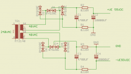
Possible PSU
The Power Supply
After much viewing of the Robert Cordell Power Supply thread on this site I came up with the following circuit
Using the Jaycar torroid MT2140
4700uf 63v caps from WES were $2 each
10,000 100v caps from WES $12.75 each
BYQ28E RS 594 4629 Diode recommended by Hugh Dean AKSA Site
The theory goes towards decoupling the DC output ground from the noisy diodes and transformer secondary, we may need the toys from the boys in order to verify this, the 25ns diodes definitly make a difference.
ALfred
Attachments
OK, I got that far successfully!alfredrofe said:It may be best to make the standard kit up then start modifying, this is get it working first.
") I ran it for a couple of hours and all went well.
I ran it for a couple of hours and all went well.A suggestion for those like me who don't have much space or equipment - I got the drill-press attachment for my Dremel, plus a small set of drill bits that can fit the Dremel's various collets. Using this plus WD-40 as lubricant I got the holes done in no time. I didn't use a tap, so I simply used tweezers to stick the nut through between the heat-sink blades. I've never drilled metal before, so it was a bit intimidating, bit by the time I did the 2nd heat-sink the whole process only took a few minutes.The kit does not come with enough screws for the complete mounting, using a cast heat-sink you may need to invest in a 3mm tap and a 2.5 mm drill to thread holes, through holes a a little difficult with the suggested heat-sink.A I have a rather extensive workshop with both sheet-metal and turning capacity I make most of my own boxes etc, but for those with limited resources seeking some help may be required or finding someone with the tools and even grater someone who will lend them to you. A challenge in deed.
OK this is where things fell apart for me...A 100R trim pot is soldered to the top track (runs diagonally towards the 1000uf cap) on the board in front of Q13 collector after cutting the track and remove the solder mask for soldering, this allows setting the bias within the better 100ma Class AB setting
I put in the trimpot (having set the resistance to 8Ohm), fired up the power again, and after 30 secs one of the 100R emittor resistors flared. I replaced it, checked for short circuits, and tried again. Now the other one flared! I haven't tried anything further yet. To cut the track, I just drilled through it using a bit wider than the track. I then scraped back the track covering on each side, and soldered directly to that (the solder didn't seem to 'stick' to it very well however). Any thought about what I may have stuffed up, or suggestions for how to do it next time? Is it OK to leave the heatsink off whilst doing these tests and modifications? The transistors didn't warm up at all in the 30 secs it took for my resistors to blow...
Have you got a diagram or something you could possibly email me? I'm still stuck on what this is meant to look like.Remove the two 100R emitter resistors on Q10 + Q11 replace with one 220R resistor and 1uf capacitor, the 1uf cap is a standard in this position and as OStripper points out you can tune the circuit to you liking. I drilled two holes in front of the transistors Q10/11, on the under side I bent the wires to join to the emitters of Q10/11 and piggy backed the cap on top of the resistor.
Many thanks Alfred!
Well, I tried undoing the change by removing the trimpot and adding a jumper over the break in the track. I also followed the advice in the SC article and replaced the fuses with 5W resistors for testing. No luck - more burnt out 100Ohm resistors!Any thought about what I may have stuffed up, or suggestions for how to do it next time?
 So I guess I've stuffed up some other component somewhere, or somehow created a short.
I think I'll chuck out this kit and get another one - at least I can still keep the PSU, bridge rectifier, and heatsink, so it's not too much money wasted. Since I bought 2 for stereo, I've already got a spare I can try again with...

The output stage in this amplifier have two major problems:
A) 7...10mV over Re is not enough for optimum classB bias level. ... try at least 15mV
B) The bias is not stable with temperature, actually the bias increase with temperature, possible runaway scenario in extreme cases, like very loud party. This case can be solved with a simple MUR120 diode thermally coupled with the heat sink and in series with all TermalTrack diodes
SC ULD2
Jeremy
The kit should first be constructed as per the published articles.
The 2nd part details changes needed. If the design still had major problems, Silicon Chip would have been inundated with complaints, as by now many kits would have been sold and constructed. Much of the advice being given here is made without knowing the published changes featured in the 2nd part of the article, or for that matter,having seen the whole project as published.
My other suggestion would be to check the Silicon Chip website for Errata for this project. Please note that I am not dismissing Alfred's modifications, howevever, IIRC, Alfred suggested constructing the kits in their published form first.
SandyK
jp_howard said:OK, I got that far successfully!
Congratulations on a job well done, do you have a mutlimeter and did you measure the voltages around the circuit as per the article with the kit, the crtical measurement for your first mod is the voltage across the 0.1R resistors, this could have been 1-6mv, if it was 7mv or higher in some cases the 100R trimpot mod would not be needed.
jp_howard said:A suggestion for those like me who don't have much space or equipment - I got the drill-press attachment for my Dremel, plus a small set of drill bits that can fit the Dremel's various collets. Using this plus WD-40 as lubricant I got the holes done in no time. I didn't use a tap, so I simply used tweezers to stick the nut through between the heat-sink blades. I've never drilled metal before, so it was a bit intimidating, bit by the time I did the 2nd heat-sink the whole process only took a few minutes.
I commend your immagination an ingenuity here, were all the transistors flat against the heatsink, did they have their pads placed correctly, the TO264 pads do not come to the edge of the plastic but are only sufficent for the metal part at the back.
jp_howard said:OK this is where things fell apart for me...
As you have no referance voltage across the 0.1R resistors, setting the pot to 8R is probably a mistake, set it to zero and increase under measurement. When you drilled through the board did you drill through a track on the bottom layer, from your description I am not convinced you soldered the trimpot correctly, an open circuit here will make everything go wild, giving you an enourmous bias.
jp_howard said:Is it OK to leave the heatsink off whilst doing these tests and modifications? The transistors didn't warm up at all in the 30 secs it took for my resistors to blow...
This is definitely the biggest No NO, the heatsink must be attatched when power is applied. The transistors may have blown in that 30 secs, however they can be checked with a multimeter to ***** their suffering.
jp_howard said:Have you got a diagram or something you could possibly email me? I'm still stuck on what this is meant to look like.
I have some diagrams but they are larger than 2meg and will not post, I can send direct if your email box is big enough, keep on DIY ing, it can only get better
Alfred
Re: SC ULD2
The Jaycar kit actually contains both articles, including the follow-up. It also contains the correct parts and PCB including the modifications. I built the kit according to those specs.sandyK said:The kit should first be constructed as per the published articles.
The 2nd part details changes needed.
Yes, I checked the voltages and they were all correct as shown in the SC article, except across the 0.1R's, which were ~2mV.alfredrofe said:Congratulations on a job well done, do you have a mutlimeter and did you measure the voltages around the circuit as per the article with the kit, the crtical measurement for your first mod is the voltage across the 0.1R resistors, this could have been 1-6mv, if it was 7mv or higher in some cases the 100R trimpot mod would not be needed.
Yes - thanks for checking. The SC article does a good job of explaining this, and also explaining how to check for shorts, which I did very carefully.I commend your immagination an ingenuity here, were all the transistors flat against the heatsink, did they have their pads placed correctly, the TO264 pads do not come to the edge of the plastic but are only sufficent for the metal part at the back.
Yes I think you're absolutely right. I'm sure I didn't drill through another track, but I'm not convinced I soldered the trimpot correctly. Can you tell me the technique for doing this correctly? Thanks for the tip about the trimpot setting BTW.As you have no referance voltage across the 0.1R resistors, setting the pot to 8R is probably a mistake, set it to zero and increase under measurement. When you drilled through the board did you drill through a track on the bottom layer, from your description I am not convinced you soldered the trimpot correctly, an open circuit here will make everything go wild, giving you an enourmous bias.
OK that's good to know for next time. It sounds like I'll be connecting and disconnecting the heatsink quite regularly - I think I better find a way to glue the nuts onto the heatsink so that it'll be faster to connect and disconnect it.This is definitely the biggest No NO, the heatsink must be attatched when power is applied. The transistors may have blown in that 30 secs, however they can be checked with a multimeter to ***** their suffering.
Please do, that would be great. My email is jeremyAThowardDOTname (replace AT with '@', and DOT with '.' of course!)I have some diagrams but they are larger than 2meg and will not post, I can send direct if your email box is big enough
- Status
- This old topic is closed. If you want to reopen this topic, contact a moderator using the "Report Post" button.
- Home
- Amplifiers
- Solid State
- Silicon Chip 200Watt LD amplifier