Re: Frugalamp
Yes, you are right.
Using big value resistors, eventually with some 0.7 V diodes to create some lower voltage reference, is many times a good enough solution.
sandyK said:lineup
It's not feasible at these much higher rail voltages, but some years ago, with a phono preamp using an SSM2220 LTP,
and +-15V rails , I achieved a very good null of the offset, simply by connecting a 20M 1% resistor between collector and base of the input device. The directly coupled MM cartridge then had virtually no DC through it.
SandyK
Yes, you are right.
Using big value resistors, eventually with some 0.7 V diodes to create some lower voltage reference, is many times a good enough solution.
ostripper said:Could also CM the VAS instead (make a big symasym)...
your VAS already has a simple CM, I assume you mean replace the diode with a transistor wired as a diode
")
The VAS doesn't leave class A, as it doesn't switch off. Finding the current that it works most efficiently at is the key. You will cut distortion by a good margin by lowering that 14mA to ~8mA.
I have taken your recommendations in 2 areas ,lowered my
VAS to 10mA (my VAS did get a little toasty when cranked)
and went back to 1.7mA for input section.
Also, I tried the 2sa1381/2sc3503 combo , and it "likes" 10ma
also, same package, better specs. (found them in crt stuff)
Frugal 1 is finalized, except maybe EF VAS.
Frugal 2 is where I want to go with the symmetrical VAS
(ampslab type Bi-120).
By AKSA -Yes, you could, and if you do, you have replicated the Hitachi Application Note from 1972 which was developed for their new mosfets, and which is used in many Class AB Pro-audio amps because it is rugged, dependable, and inexpensive
Yes, that is where I think ampslab "ported" that design from.
PS... new update to frugal 2 soon.
OS
ostripper said:
I have taken your recommendations in 2 areas ,lowered my
VAS to 10mA (my VAS did get a little toasty when cranked)
and went back to 1.7mA for input section.
Hi OS,
I didn't say anything about the input section, just that there was a 1 watt resistor there and that the way you had the 3rd transistor on the CM configured didn't work for me in simulation.
Running the differential pair at a higher current (within limits) seems to be beneficial.
Using the 2SA1381 for VAS, you can get away without the EF. Simulation says it is much improved.
ostripper said:Also, I tried the 2sa1381/2sc3503 combo , and it "likes" 10ma
also, same package, better specs. (found them in crt stuff)
Frugal 1 is finalized, except maybe EF VAS.
Also, if you need to buy some new parts, Mouser charges less for the KSA1381/KSC3503 than they do for the MJE340/MJE350.
Symon said:Just an observation, but the voltage gain of the inverting side of the input pair is very low compared with the non-inverting side. because the dynamic impedance of the current mirror input is low, compared to the output impedance.
It will work, but you aren't really driving the VAS with equal / balanced signals.
That’s exactly what I said; the reason why I used a current mirror tail for the VAS so as to avoid modulation of the tail current.
With that matter addressed, with regards to driving the differential VAS with unequal signals it really doesn't matters as a differential amplifier is only interested in the difference between its inputs. Distortion is still lower (over a "balanced" resistive load arrangement) as the CM loaded LTP gain is much higher and the LTP doesn't work nearly as hard.
Cheers,
Glen
AKSA said:However, this will alter OLG of the LTP, in turn changing compensation by reducing fb factor. You will need to reduce the lag compensation to accommodate this change.
Completely wrong. You will only need to alter the compensation (WRT LTP gain) if the gm of the LTP is altered.
Cheers,
Glen
By andy c. - Also, if you need to buy some new parts, Mouser charges less for the KSA1381/KSC3503 than they do for the MJE340/MJE350
Mouser is a good company, free air at ground rates for new customers . Good prices too, that's how I built these for 21$
apiece.
you guessed right..next post..by Symon - your VAS already has a simple CM, I assume you mean replace the diode with a transistor wired as a diode
OS
G.Kleinschmidt said:
Completely wrong. You will only need to alter the compensation (WRT LTP gain) if the gm of the LTP is altered.
Cheers,
Glen
Glen,
This is right, remember Aksa noted that after removing the Current Mirror the gain in the LTP will decrease now that it is R loaded, with lower fb factor the lag does not need to remain as large as the OLG as a whole has now decreased. If it were the opposite, replacing passive with a CM, then you would increase lag comp. The ever lasting balance between FB factor and the need to lower the dominant pole as olg is increased, you know this very well..

Colin
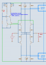
Here it is.. I want it.
This is what I want for a amp,they say this is tricky to build,
but it should sound golden. After a lot of research , it seems
if the bandwidth/gain of the 2 sides of the VAS are not equal a "pole-zero
doublet" will be formed. This must be why one must compensate
at the 'backside" of the VAS. I know it has been done,
in fact , some very good amps have a similar topology.So, I'll give it a shot,best way to learn, build it..
I've yet to choose my miller comp.
OS
An externally hosted image should be here but it was not working when we last tested it.
This is what I want for a amp,they say this is tricky to build,
but it should sound golden. After a lot of research , it seems
if the bandwidth/gain of the 2 sides of the VAS are not equal a "pole-zero
doublet" will be formed. This must be why one must compensate
at the 'backside" of the VAS. I know it has been done,
in fact , some very good amps have a similar topology.So, I'll give it a shot,best way to learn, build it..
I've yet to choose my miller comp.
OS
vynuhl.addict said:
Glen,
This is right, remember Aksa noted that after removing the Current Mirror the gain in the LTP will decrease now that it is R loaded, with lower fb factor the lag does not need to remain as large as the OLG as a whole has now decreased. If it were the opposite, replacing passive with a CM, then you would increase lag comp. The ever lasting balance between FB factor and the need to lower the dominant pole as olg is increased, you know this very well..
Colin
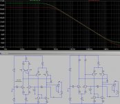
No it isn't right. With miller (lag) compensation increasing the open loop gain by decreasing the loading on the long tail pair does not change the unity loop gain frequency or stability – it decreases the open loop bandwidth.
Attached below is a simulation of two differential VAS op-amps (with the same 68pF miller comp cap in each).
Op-amp A (green trace) has the current mirror LTP. Op-amp B (red trace) has a pair or resistors instead.
So no, by getting rid of the current mirror you will not be able to get away with a smaller miller compensation capacitor.
If you wan't to get away with a smaller miller comp cap then you will have to reduce the LTP's gm by increasing its emitter degeneration. This is fundamental.
Attachments
Ostrpper,
It looks good, love to see people out there building ideas, no better way to learn than hands on. C4 will of course take some heat off of the miller compensation cap and thats where the compensation gets fun, experimenting with the values/ration of each. The only change I would make is to tap C4 15pf off of the VAS output to the inverting base of the LTP, aside from that time to build!.
Colin
I see you use150R emitter for input pair.
At 2.2 mA you have drop >300 mV
If you read D. Self blameless input stage, you see he have 'only' 68 mV drop at one case.
This would be like you using 33R.
It is good to have a bit higher gain in input stage.
Because this is high quality gain = Fast transistors. low noise and good linearity.
Lower your emitter resistors from 150R to 33R / 47R
will increase Gain in first stage with a factor 3-4.
----------------
I am sure you studied my attach circuit very closely
but here it is again
I have 4 input transistors. Each of them is operating at a gain a bit less than x50. (5000 Ohm /100 Ohm)
As I run them at 1 mA, the drop across emitter resiistors is: 1 mA x 100 Ohm = 100 mV
I do not know if my input stage contributes 4x50 = Gvolt 200
Or if the contributed gain is only x50.
Glen, you can tell me, please. thanks
Lineup
Attachments
Thanks , vynuhl.addict, I'm building the sim now. Just to see if I'm in the ballpark.
As far as C4 , you mean FULL NFB right from the VAS?? I've seen
that in some amps, but not many. maybe for the best for this
topology has a lot of OLG.
I'm pulling my hair out for a strange reason, these NJW
OP devices have some new plastic that acts as an insulator
interfering with my Vbias generator. I can't feel heat on the body
of the devices but the heatsinks are plenty warm.
I played with the Vbias ratio but it is right for a
BD139 (symasym amp uses my exact values, I noticed).
So, I'll try to mount on HS, see if that corrects issue.
Pete,
Remember that as you increase gm of the input stage by reducing emitter degeneration, OLG for the whole amp will increase, and miller comp will need to be bumped up slightly.
Self says that a CM will give 6dB more OLG, and so the same argument applies here. I've found that LTP degeneration has profound influence on lag comp, so be careful, don't connect up a speaker until you examine the output on a CRO, or at the least feel for heat on a Zobel resistor (put in 10R/100nF, it's excellent practice and a good detection tool for HF oscillation).
Good going, nearly there......
Hugh
ostripper said:Lineup, you mean MY emitter degens??? Put in 47R to give more gain?? I'll try it.
Ugh. Did you read my post 111?
If you change the emitter degeneration from 150 ohms to 47 ohms you will need to increase the miller cap pretty much proportionally (not "slightly") to maintain the same unity loop gain frequency (unless you increase the closed loop gain ~proportionally instead, which you likely would not like to do).
Cheers,
Glen
Glen ,I had no idea which amp lineup was referring to ,1 or 2.
And being very tired, browsed right through yours.
I see you are a more advanced user of Pspice software , which do you use.?
Have patience,maybe the LTspice I have sucks, are there better.
I'll get it pronto.
Also, very hard to see your sims...
sorry..
And being very tired, browsed right through yours.
I see you are a more advanced user of Pspice software , which do you use.?
Have patience,maybe the LTspice I have sucks, are there better.
I'll get it pronto.
Also, very hard to see your sims...
sorry..
ostripper said:Glen ,I had no idea which amp lineup was referring to ,1 or 2.
And being very tired, browsed right through yours.
I see you are a more advanced user of Pspice software , which do you use.?
Have patience,maybe the LTspice I have sucks, are there better.
I'll get it pronto.
sorry..
OK. I'm using a year old + version of LT spice (to lazy to update because the downloadable updates take tooooo long
 ). Have a look in the example folders. The are some good files there (called "loopgain" or such) showing how to sim the (closed) loop gain and phase of an operational amplifier.
Cheers,
Glen
I did that. In fact, I knew of the OLG/compensation ratioby AkSA - least feel for heat on a Zobel resistor
previously, by looking at a thousand amps.
I know I shouldn't learn like this , but I often go through the
"back door" first to get it done, then learn the theory.
I know there an equation for this relationship.
Thanks, dean...
And Glen, I'm really not a dummy, just 3 hrs. sleep in 48..
OS
- Status
- This old topic is closed. If you want to reopen this topic, contact a moderator using the "Report Post" button.
- Home
- Amplifiers
- Solid State
- The Frugalamp by OS