About to make boards... VAS was much harder to lay out than
regular "blameless" ,but more fun (hairpulling)to get all devices
in one group.(very dark blue line)Also, full thermal coupling of
VAS and "face to face" LTP coupling.

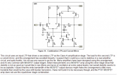
Input and ground optimized with enough room to even
get 330u/100v decoupling caps and a huge input cap
on the board.
This may seem primitive, but I plan to copy this on PSP or eagle
after I determine these amps are idiotproof. frugalamp 1 is
doing the HT thing for the kids everyday so If you build it
NO BS..
OS
regular "blameless" ,but more fun (hairpulling)to get all devices
in one group.(very dark blue line)Also, full thermal coupling of
VAS and "face to face" LTP coupling.
Input and ground optimized with enough room to even
get 330u/100v decoupling caps and a huge input cap
on the board.
This may seem primitive, but I plan to copy this on PSP or eagle
after I determine these amps are idiotproof. frugalamp 1 is
doing the HT thing for the kids everyday so If you build it
NO BS..
OS
OS,
Please try to put the output stage decoupling electrolytic capacitors as close as possible. The ground line between them is highly polluted with harmonics from half sine wave output signal.
The middle point of this ground line should be connected to the star ground.
Mihai
Please try to put the output stage decoupling electrolytic capacitors as close as possible. The ground line between them is highly polluted with harmonics from half sine wave output signal.
The middle point of this ground line should be connected to the star ground.
Mihai
Yes , very dirty ground. That why the differential is away from it,
zoble is separate (daughter board) ,speaker return on a
separate wire. Have a small case,small board, certain compromises had to be made. still, NFB takeoff is right in the
middle , very short LTP to VAS traces, Cdom riding the 2sa1381's
and 22R buffered small signal ground. I even put the CCS
near the "dirty ground" with decoupling...
You are right, I would of put bigger (470uf +),closer together,
decouplers if I had more real estate. I might run a 18ga
wire from C/v+ - G - C/v- to tame some of that ripple.
thanks for comment...OS
One step closer,primitive sharpie and some paint....A little fine
artwork..
A few little bridged patterns to "scratch" away,these are the
last ones I'm going to do like this as I anticipate further
complexity in the future ,(my new protection circuit).
Off to get a laser printer...
This is the final schema that simmed perfectly with a little extra
compensation and it is what the board will reflect.
OS
artwork..
An externally hosted image should be here but it was not working when we last tested it.
A few little bridged patterns to "scratch" away,these are the
last ones I'm going to do like this as I anticipate further
complexity in the future ,(my new protection circuit).
Off to get a laser printer...
This is the final schema that simmed perfectly with a little extra
compensation and it is what the board will reflect.
An externally hosted image should be here but it was not working when we last tested it.
OS
Hi John,
C3 carries the AC line ripple to R7/R8, ensuring any noise is equally presented to anode and cathode of the voltage reference LED. C4 gets rid of any HF noise created by the LED - tiny anyway, frankly I don't bother with C4, but C3 confers strong benefits.
The part I find interesting is R11/R12, which load down the VAS, limiting OLG and thus closely controlling fb factor. This would make it very tolerant of semiconductor choice, keeping costs low. C13 and C12 brutally load down the VAS at HF, serving as compensation. I suspect this sort of compensation might sound better than C5/C6; I'm sure Pete has got the balance just right using LTSpice.
Pete, how did you arrive at the size of R16? I recall GK suggested 470R; you've gone a full order of magnitude higher..... any reason for this?
Cheers,
Hugh
C4,C3 If I could omit them , I would. They keep voltage and
current fluctuations down to pA's and uV's both in the real world
and in spice. Without them you would have a quasi amp with
barely 60db PSRR. I first saw the 22uf (C3) on the "blameless"(D.self) It lowers psrr in the CCS by 20db.
C4 is a remnant from frugal 1, when followed by a 1-2K resistor to
the VAS "lower leg" it dampens the phase lag of the CCS vas.
I decided to leave it as it does filter out HF as well.
One ??? to you MJL .is the reason for your cascode in "patchwork" to reduce gain?? Your 2sa1381's are such
high gain that I could not imagine using a EF to drive them.
(1- 1381 almost equals a mje350/w EF in gain)
oS
ostripper said:
One ??? to you MJL .is the reason for your cascode in "patchwork" to reduce gain?? Your 2sa1381's are such
high gain that I could not imagine using a EF to drive them.
(1- 1381 almost equals a mje350/w EF in gain)
oS
Thanks for the explanation, AKSA.
The cascode on the LTP? It originated from me not having any high voltage/ high gain T's for the differential pair. It made it possible to use the BC550 then the LM394 super matched pair.
I've stuck with it, even though I now have some good high gain/high voltage devices (ZTX696B).
The good thing about having a lot of gain, I guess, is that you can afford to throw some away.
R16... I started at 470rBy AKsa -Pete, how did you arrive at the size of R16? I recall GK suggested 470R; you've gone a full order of magnitude higher..... any reason for this
and went to 10k while looking at currents sourced and sinked
from the diff. , VAS
linearity and overall phase/current balance of each side of the
VAS and HOW they changed with frequency(20hz-100khz).4K7 seems
to be the "happy middle" where those factors were at their best (1-2uA LTP, 5 uA between sides VAS). With just a standard
CM on the VAS these values are 50 times higher and change
with frequency.
BTW ..I use the same KSA1845 for the widlar buffer and at
full power sinks the same as LTP (1.5ma) balance all around.
OS
As far as r11/12 , c12/13 , thats a good question. first saw this
on the "symasym" wondered why, simmed it.
this is what I found..
1. It slightly decreases the phase margin,
2. lowers the unity gain point,
3. rolls off gain above 1Mhz (drops off scale after 2mhz)
4. Slew rate drops off (very predictable)
What would be the added benefits of this??
I really don't know, Aksa explained that this might give the circuit
more room to be "sloppy" (components choices,etc.)
As far a loading down anything , I have a "beast" of a VAS.
I might try this type of compensation
by itself but really I just wanted to have the pads available
to see how the real circuit would react.(better safe than sorry)
This "gross" compensation is what gives the symasym the
sound that makes it the favorite among some of the senior
audiophiles here at DIY..even tube lovers.
Having simmed many combinations of this "gross" compensation,
I must say it has predictable effects which I will actually have to
hear/see in the real world. As it is now, my range is all the way from the bogged down version (symasym, this amp) to
the ampslab BI240 (22pf Cdom/ 100v-uS+ slew/2mhz UGP)
all these mods seem to sim very well with this design even with crazy loads(LCR), simulated ripple on rails,etc.
OS
ostripper said:As far as r11/12 , c12/13 , thats a good question. first saw this
on the "symasym" wondered why, simmed it.
Having simmed many combinations of this "gross" compensation,
I must say it has predictable effects which I will actually have to
hear/see in the real world. As it is now, my range is all the way from the bogged down version (symasym, this amp) to
the ampslab BI240 (22pf Cdom/ 100v-uS+ slew/2mhz UGP)
all these mods seem to sim very well with this design even with crazy loads(LCR), simulated ripple on rails,etc.
OS
Funny, I don't see it on the Symasym 5.3 schematic.
Symasym, even with it's compensation, seems to be inherently unstable. I have tried seven ways from Sunday to tame it in my sim, but to no avail.
Here's what Rod Elliot has to say:
Attachments
Here they are..MJL
I only used the symasym as a reference
design.
mike B. uses 330p/47k (gross compensation to reduce HF gain)
and only 1 Cdom (100p)at the "back end"
of the vas(that has the smell of instability.. doesn't it?)
I believe both Douglas self and rod elliot either
didn't want to put forth the effort or saw the design as too much
of a challenge for the average hobbyist as one can plainly see in both their writings.I notice R. elliot contradicts himself in his
statement saying it has better linearity but no added benefits
..what??? he fails to mention equal loading of the LTP , then
he says it "might " show instability with certain OP's
or at clipping (he describes all amps here) , but to contradict
himself again, he says stability would be acceptable with a BJT OPS.. .
Now on the other end of the spectrum ampslab's two "flagship"
amps (bi120/240) are impressive with a topology similar to
mine. Sim mine exactly,you will see no flaw (all the way down to
33pF Cdom/1.2Mhz UG) Below 33pF I see slight ringing but even this can be
reduced or eliminated by playing around with OLG
and phase.(ampslab "magic" LTP RC bridge)
As I explained earlier I only added those "gross comps" to
"play with" when it is done.
BTW, I had no problem modeling the symasym after giving it
matched Cdoms (same as mine, elliots has no Cdom )
)
just to see how/why it worked.
OS
An externally hosted image should be here but it was not working when we last tested it.
I only used the symasym as a reference
design.
mike B. uses 330p/47k (gross compensation to reduce HF gain)
and only 1 Cdom (100p)at the "back end"
of the vas(that has the smell of instability.. doesn't it?)
I believe both Douglas self and rod elliot either
didn't want to put forth the effort or saw the design as too much
of a challenge for the average hobbyist as one can plainly see in both their writings.I notice R. elliot contradicts himself in his
statement saying it has better linearity but no added benefits
..what??? he fails to mention equal loading of the LTP , then
he says it "might " show instability with certain OP's
or at clipping (he describes all amps here) , but to contradict
himself again, he says stability would be acceptable with a BJT OPS..
.Now on the other end of the spectrum ampslab's two "flagship"
amps (bi120/240) are impressive with a topology similar to
mine. Sim mine exactly,you will see no flaw (all the way down to
33pF Cdom/1.2Mhz UG) Below 33pF I see slight ringing but even this can be
reduced or eliminated by playing around with OLG
and phase.(ampslab "magic" LTP RC bridge)
As I explained earlier I only added those "gross comps" to
"play with" when it is done.
BTW, I had no problem modeling the symasym after giving it
matched Cdoms (same as mine, elliots has no Cdom
)just to see how/why it worked.
OS
Hi,'
I would not say that.Loading the VAS with resistors to ground is a big mistake.
They do but may favourably affect the sound in real life.you will see on simulation that those resistor will badly affect THD.
Lumba Ogir said:Hi,'
They do but may favourably affect the sound in real life.
Only if you like how H3, H5, H7, H9 sound
- Status
- This old topic is closed. If you want to reopen this topic, contact a moderator using the "Report Post" button.
- Home
- Amplifiers
- Solid State
- The Frugalamp by OS