Hello
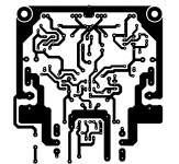
I was busy with a similar project like these, just finished the PC boards layout.
The main reason I stopped work on these project I need to order some exotic parts to the final amp at the same time I place the order for other project.
Also I did return some old parts to PartsConnexion for exchange so I must place the order I ASAP.
I have to mention by the help of Wahab the circuit was a bit modded (I think you built your amp based on that, you know that) but by me that was never tested (yet).
So really I do not know sound wise it was a upgrade or not or the same how it was.
I'll test it soon.
Also want to compare the sound of the amp with the LC type since that became so popular.
By the way Marc built the discrete darlington amp modded by Borys from LC LatFet version and he wrote he get the best balanced sound around 50mA bias.
Knowing that I really have to re test these amplifier to.
Do we really need that high bias? The amp stable with low bias with a adequate heatsink.
I do not think other people work on the orig project now.
Greetings Gabor
I keep checking on progress on the LC type circuit. I recently read something about shorting out some resistors and that it resulted in better bass. But they said earlier that it has superb deep bass and bass control. So it got noticeably better by removal of some components ?
All this is so confusing as we really don't know what the reference system is.
I can say that your 20 year old circuit sounds great and can be improved with some refinements. I can't say now if the refinements only made an improvement in measured performance and nothing audibly. I can't even say if the simplest configuration sounds better ! This is possible. Remember that the typical resistor load with bootstrap on the VAS sounds nicer than a CCS load on the VAS in some circuits. Poorer measurement but better sound !
I'm trying out the ex-plendit version of your circuit. The input transistors are turned around. The rest appears to be similar.
Cheers.
Approaching completion. Board is ready. Needs to be fixed to the heat sink. Same board size and heat sink as used for the '20 year old amp' !
I plan to try it at 50 to 80 mA bias. I just flipped the input transistors and reconnected the input stage. It's a new board. Trust there are no errors.
Supply will be +/- 36 to 40 V depending on our mains supply !
I plan to try it at 50 to 80 mA bias. I just flipped the input transistors and reconnected the input stage. It's a new board. Trust there are no errors.
Supply will be +/- 36 to 40 V depending on our mains supply !
Ashok
can you post the circuit please, easier to follow or understand any mode you made. Also we can refer to the circuit any time.
I will test soon these version.
Let see if that make these little amp more stable and sound wise how much it will change.
I have the layout for these, was designed so I can test the Toshiba 2SJ201/2SK1530 MosFet to.
Only reason I do further test to see if I can get the amp a bit more stable with Class A/B bias
Honestly I'm more than satisfied of the sound of the amp using the latest semiconductor set.
Greetings Gabor
Attachments
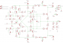
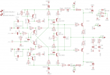
Here is the circuit. It's been copy pasted from the Beige Bag Spice program.
I've attached the power supply rejection ratio of the circuit with RC filtering for the input stage and the same stage with a capacitance multiplier attached to the input stage . My current board is with the capacitance multiplier. I can disable it later to see how it sound.
From the graph you can see a huge improvement in the PSRR at LF with the cap multiplier.
Curves: Red -- + ve rail PSRR with plain RC filter
Grey -- - ve rail PSRR with plain RC filter
Blue -- + ve rail PSRR with cap multiplier
Green -- - ve rail PSRR with cap multiplier
Attachments
Last edited:
Hi G,
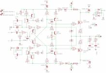
There is a small error in the first circuit with the 22 ohm compensating resistor. The Q12 base must go to the collector of the BD139 bias transistor Q50. Otherwise the resistor will not have any effect.
Thank you
I just left out that compensation resistor, probably not even need to be used in these circuit.
I remember when you wrote about (U used it at the basic circuit) so I put it in to the circuit to remember about that 22R and I forget there.
I will take a look at your new circuit
") , didn't had time yet.....
, didn't had time yet.....Greetings Gabor
Attachments
Here is the circuit. It's been copy pasted from the Beige Bag Spice program.
I've attached the power supply rejection ratio of the circuit with RC filtering for the input stage and the same stage with a capacitance multiplier attached to the input stage . My current board is with the capacitance multiplier. I can disable it later to see how it sound.
From the graph you can see a huge improvement in the PSRR at LF with the cap multiplier.
Curves: Red -- + ve rail PSRR with plain RC filter
Grey -- - ve rail PSRR with plain RC filter
Blue -- + ve rail PSRR with cap multiplier
Green -- - ve rail PSRR with cap multiplier
Thank you for the circuit. I love it!!!!!!!
You invented some nice idea there.
Let see how will effect or how much will improve the basic circuit.
Greetings Gabor
Good news. I have been playing the amp for the last 3 hours. Sounds very good.
Can't say the difference between this and your earlier circuit. Sounds same without an A/B comparison. Basically , very good !
Bias is set at 50 mA and it is quite stable even with a silver heat sink ( like the earlier one ) facing downwards. Will try it with lower bias ( or no bias !) and at 100mA at a later point of time. Maybe TIP 142/147 don't like high bias settings at +/- 40 V.
I now need to check all dc currents. I did make some parts changes as I didn't have the right ones at hand. Must record it so that I remember what they were.
I want to check it with no input cap and with better caps ( Solen, Mundorf Supreme and some PIO's ) Just want to see what happens. The current one is a polyester 1uF 450V cap. I found it worked very well in another circuit.
I suggest you include the 22 ohm resistor and short it out if not required. Can't add it easily later if required. I've decided to use it as it does keep the bias from drifting up alarmingly as the heat sink heats up. Maybe with a large heat sink it will not be required but then I can short it out later. In any case it doesn't affect the audio performance.
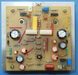
My input transistors are BC546B/BC556B. Drivers are 2SC4793 / 2SA1837. Output of course is TIP142/TIP147 . Emitter resistors on the output stage is 0.33 ohms. No output inductor. Bias transistor is BD139. Cap multiplier transistors are BD139/BD140. This is an over kill. A small signal transistor would do ! PCB size could be reduced too.
Must build one with discrete Darlington and working on rails up to +/- 50 volts or so. Will need more power transistors. Ideally will need protection circuitry for shorts etc. Mine is externally protected for dc with a relay. Supply caps are 20,000uF /50 V per rail.
Now I must run. Time to get dinner ready! It's already terribly late.
Cheers.
Forgot to add the usual. No hum or hiss right at the speakers . I can hear 'some' noise at the tweeter at 1 inch from the dome. Not audible at a foot from it. It isn't a 'sssss' but a dull 'shhhh'. REALLY faint ! I'd class it noiseless at 1 foot from the speakers !
Can't say the difference between this and your earlier circuit. Sounds same without an A/B comparison. Basically , very good !
Bias is set at 50 mA and it is quite stable even with a silver heat sink ( like the earlier one ) facing downwards. Will try it with lower bias ( or no bias !) and at 100mA at a later point of time. Maybe TIP 142/147 don't like high bias settings at +/- 40 V.
I now need to check all dc currents. I did make some parts changes as I didn't have the right ones at hand. Must record it so that I remember what they were.
I want to check it with no input cap and with better caps ( Solen, Mundorf Supreme and some PIO's ) Just want to see what happens. The current one is a polyester 1uF 450V cap. I found it worked very well in another circuit.
I suggest you include the 22 ohm resistor and short it out if not required. Can't add it easily later if required. I've decided to use it as it does keep the bias from drifting up alarmingly as the heat sink heats up. Maybe with a large heat sink it will not be required but then I can short it out later. In any case it doesn't affect the audio performance.
My input transistors are BC546B/BC556B. Drivers are 2SC4793 / 2SA1837. Output of course is TIP142/TIP147 . Emitter resistors on the output stage is 0.33 ohms. No output inductor. Bias transistor is BD139. Cap multiplier transistors are BD139/BD140. This is an over kill. A small signal transistor would do ! PCB size could be reduced too.
Must build one with discrete Darlington and working on rails up to +/- 50 volts or so. Will need more power transistors. Ideally will need protection circuitry for shorts etc. Mine is externally protected for dc with a relay. Supply caps are 20,000uF /50 V per rail.
Now I must run. Time to get dinner ready! It's already terribly late.
Cheers.
Forgot to add the usual. No hum or hiss right at the speakers . I can hear 'some' noise at the tweeter at 1 inch from the dome. Not audible at a foot from it. It isn't a 'sssss' but a dull 'shhhh'. REALLY faint ! I'd class it noiseless at 1 foot from the speakers !
Last edited:
Thank you for your feedback.
When you increase the Emitter resistor value from 0R22 to 0R33 that give more protection to the power transistors but somehow cut into the dynamics and bass area.
If you can test it please it would worth a try.
That was my experience from earlier tests.
Please do not forget the TIP darlingtons only was chosen as a replacement to the BDW because widely available from ST here in N America.
BDW is more in European market type but Philips or Texas Inst. no longer in production.
Only ST can be used, I did tried from some new product from other comp. like ISC but those are garbage sound wise and many of them blew up! My friend sent those from Germany.
I do have BDW83C/84C from Ebay Canada $1/piece, (I got them not to long time) if they are orig. those are a bit more rugged if my memory serve well.
I used to use those in Europe after Philips & Tex. Inst. stop producing BDW-s.
By the way I have some Sanken MP1620/2488 I'll test those soon.
To me those drivers for VAS U chose didn't not much the sound of MJE243/253. They work good but.....
Again in these simple circuit using different parts can be major factor, that is my experience based on tests I had done.
Also I have some MJ11015/16 & MJ11032/33 from ON Semi in TO3 case need to be tested but knowing the fact those are more industrial type of darlingtons have to find some extra ************ to start test them.
I did tested the discrete darlington in these circuit and I got lost.
The bass rolled of, the dynamic gone so on. I have to mention I made only one test with the transistors I had at hand.
The power transistor was some MJL type Motorola, I do not remember about the driver.
Today I have more semis at hand so I must test it again and do it properly.
If you have Russian PEPT K73-16 caps please give a try as a signal cap.
Greetings G
I saw this post just before going to bed. I'll try the discrete Darlington and see the difference. I have some extra heat sinks.
I removed the input cap and played the amp. Sounds even better ! My DVD player has caps on it's output. The offset at the input of my amp was -7mV. After removing the input cap I got -15mV at the output of my amp which I nulled out to 0.000V . It's late at night so I could not play it loud. Will try tomorrow. I think the sound is great. But I need more power !
Maybe my Eminence CX10 OB speaker will play well with it ! Actually both my larger bookshelf speakers play quite loud with the amp.
Cheers.
Of course to bring out the best from any amplifier need (to be matched) with the right speakers.
I feel like seat on needles until you compare the two circuit, of course take your time..
Do you notice way any offset drift at 50mA bias, probably with that bias will be rock solid.
That would be a great fund, great improvement.
Thank you for the feedback
Greetings Gabor
I feel like seat on needles until you compare the two circuit, of course take your time..
Do you notice way any offset drift at 50mA bias, probably with that bias will be rock solid.
That would be a great fund, great improvement.
Thank you for the feedback
Greetings Gabor
Hi G,
Offset seems to be quite stable. I set it for 0.000V and it shifted by about +2mV over a 4 hours period. Will try today and see what it is. But I think dc offset at the output isn't a problem at all. I have another DMM which can show below 1mV and will try the amp with that. Will need to use a coupling cap at the input to ensure no dc at the input.
I also want to build the P3A to see how it will compare. Using the same input transistors and drivers. Maybe 2SC5200/2SA1943 for outputs. I have several of those. We also get TTC5200/TTA1943 . These are apparently made in China but from Toshiba. I would expect them to be as good.
I am surprised that the cheap input cap actually sounds quite good ! But of course no cap sounds better !
Cheers.
Emitter resistors are metal film and not wire wound. There is a small heat sink on the drivers. Not shown here. Just one strip of 1mm aluminum about 3 inches x 1.5 inches. Maybe not required at all but due to the original worry about bias drift I added it in case it did help.
Attachments
Last edited:
Bias was set to about 50 mA when cold. After a few hours it settled at about 46mA . Ambient was 32 deg C. ( we are having unusually hot weather for this time of the year!) After playing at medium volume for an hour the small silver heat sink temp rose to 42 deg C . Bias current was about 70mA and started dropping soon after the signal was removed. Output dc offset never seemed to vary beyond +/- 3mV.
The input polyester cap is surprisingly good. Decent lows and extended HF. Poor coupling caps can dull the sound and strip away the low end.
Most important however is it's performance in the midrange and voice. Unfortunately the polyester cap made the voices less smooth and also was 'shouty' when the midrange became busy with multiple voices and sounds.
A direct ( no cap ) connection to the source cured all that! Have not yet tried any other caps in this position.
Now we need to try the amp like Acca set it. No bias current in the output stage !
All together how you like the sound.
May be you need to set up a channel (can be the basic first circuit if you still have that at your hand) and star to compare to that and now on any mode you do.
You know mind can play tricks on us, also human ear very fast adopt to the new amplifier sound specially if does not have huge difference between the two amp.
I think you know that very well.
Look like you did improved the amp stability a lot.
Thank you.
Now we need to know how does compare sound wise to the basic circuit.
I'm interested on the P3A project to, I made the PC boards for that a few months a go.
I have a good layout if you interested please let me know.
I can't and I do not want to post that due to respect to Mr. Elliot but if you want to take a look please PM to me for that.
Are you interested to send you BC550C/560C MJE243/253 so you be able to test my original amplifier.
To me those semis was a huge step forward.
I can send those small parts in a envelope.
If you have layout for your final version work and you willing to share it please post it.
Who knows someone would need for a start.
Of course that is your work and all up to you.
Greetings Gabor
Hi G,
Thanks for the offer for sending transistors. I had plans to get them from somewhere nearby. If they fail I'll let you know. I have BC550C and the BC560C MUST be in one of my parts boxes. I've started going through all my stock. I must have over 25 of them ! Oh..Oh...I forgot. I bought BC560C when I was in Colombo a few weeks ago ! So I have them now !
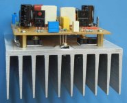
I have the first board and will try it out later today. I had pulled out the power transistor. There was a lot of track cutting etc on it. Will have to fix all that and check it before power up. I'll make a couple more boards for use with different transistors. Luckily I have the spare heat sinks , though that wouldn't have been much of a problem as the boards are easily removed.
Basically I want to decide which configuration I want and will then make a pcb with power supply on board. I like psu's on board ! Not sure if I should provide space for short circuit protection.
I am fairly certain that both amp circuits sound the same. bass is deep and tight and mids and HF is very nice. No loss on HF transients and HF shimmer is there when present ! Doesn't make the amp sound bright and clinical.
What I need to see is if the circuitry like CCS at the input and/or cap multiplier improves the sound or doesn't affect it or even degrades the sound !
One the very first test on the first board the bias current around 100mA used to slowly keep rising till power was turned off. This also happened with lower bias but when the heat sink was hot after playing music. Didn't wait for the devices to blow but it did happen a couple of times when I wasn't watching it ! I haven't yet tried the new board with the 22 ohm resistor at 100mA. Maybe I will do that before putting back the old board. But I'll have to paint the heat sink black before that.
About pcb layouts. Right now I don't want to make anything new. The next several days I am pretty busy. I'll let you know when I might want to try them out. I'm again out of town in 3 weeks time for a couple of weeks. So I need to finish what I have at hand. My new OB speakers are still incomplete! Bugs me a lot.
Cheers.
Thanks for the offer for sending transistors. I had plans to get them from somewhere nearby. If they fail I'll let you know. I have BC550C and the BC560C MUST be in one of my parts boxes. I've started going through all my stock. I must have over 25 of them ! Oh..Oh...I forgot. I bought BC560C when I was in Colombo a few weeks ago ! So I have them now !
I have the first board and will try it out later today. I had pulled out the power transistor. There was a lot of track cutting etc on it. Will have to fix all that and check it before power up. I'll make a couple more boards for use with different transistors. Luckily I have the spare heat sinks , though that wouldn't have been much of a problem as the boards are easily removed.
Basically I want to decide which configuration I want and will then make a pcb with power supply on board. I like psu's on board ! Not sure if I should provide space for short circuit protection.
I am fairly certain that both amp circuits sound the same. bass is deep and tight and mids and HF is very nice. No loss on HF transients and HF shimmer is there when present ! Doesn't make the amp sound bright and clinical.
What I need to see is if the circuitry like CCS at the input and/or cap multiplier improves the sound or doesn't affect it or even degrades the sound !
One the very first test on the first board the bias current around 100mA used to slowly keep rising till power was turned off. This also happened with lower bias but when the heat sink was hot after playing music. Didn't wait for the devices to blow but it did happen a couple of times when I wasn't watching it ! I haven't yet tried the new board with the 22 ohm resistor at 100mA. Maybe I will do that before putting back the old board. But I'll have to paint the heat sink black before that.
About pcb layouts. Right now I don't want to make anything new. The next several days I am pretty busy. I'll let you know when I might want to try them out. I'm again out of town in 3 weeks time for a couple of weeks. So I need to finish what I have at hand. My new OB speakers are still incomplete! Bugs me a lot.
Cheers.
No Bias test!
First of all , after playing the amp at clipping for about 20 minutes the dc bias was 153mA,measured as soon as the music was stopped. The heat sink was at 53 deg C and in it's worst possible position ( face down). No air draft around the unit. As soon as it was measured the current started to drop unlike on the very first board I had tried. Sound was very good .
Load was a Behringer 2031P which is rated at 4 ohms ! Amp supply voltage was +/- 39 Vdc.
Then I did what Acca requested. I dropped the bias voltage to 1.9 V ( between bases of the output Darlington transistors). I still had a residual voltage of 6mV across the two emitter resistors ( 2x 0.33 ohms). That would be about 9mA. Not sure if this was an error but the output stage was surely not in any classAB condition.
I played the same track at the same level. I couldn't hear a difference ! Low level HF sounds same ,bass is deep and tight AND more importantly the voice didn't get harsh or grainy . It appeared to be the same. Even at low volume it appears to be fine. I must check this on a FFT to see if what we hear and measure correlate with each other . I didn't really expect this!I thought that it might sound OK but inferior. But it doesn't seem to be so. Must try tracks from several different albums. If this is real , it's great. No bias transistor required or have any thermal issues !
Going from the earlier 50 mA bias to the 100mA bias of this test I thought it was good but really didn't listen carefully for any differences between 50 and 100mA. But now it looks like it didn't matter !
Hmm.....I need to look at this very carefully.
Acca, if you are reading this ..... You were right.
First of all , after playing the amp at clipping for about 20 minutes the dc bias was 153mA,measured as soon as the music was stopped. The heat sink was at 53 deg C and in it's worst possible position ( face down). No air draft around the unit. As soon as it was measured the current started to drop unlike on the very first board I had tried. Sound was very good .
Load was a Behringer 2031P which is rated at 4 ohms ! Amp supply voltage was +/- 39 Vdc.
Then I did what Acca requested. I dropped the bias voltage to 1.9 V ( between bases of the output Darlington transistors). I still had a residual voltage of 6mV across the two emitter resistors ( 2x 0.33 ohms). That would be about 9mA. Not sure if this was an error but the output stage was surely not in any classAB condition.
I played the same track at the same level. I couldn't hear a difference ! Low level HF sounds same ,bass is deep and tight AND more importantly the voice didn't get harsh or grainy . It appeared to be the same. Even at low volume it appears to be fine. I must check this on a FFT to see if what we hear and measure correlate with each other . I didn't really expect this!I thought that it might sound OK but inferior. But it doesn't seem to be so. Must try tracks from several different albums. If this is real , it's great. No bias transistor required or have any thermal issues !
Going from the earlier 50 mA bias to the 100mA bias of this test I thought it was good but really didn't listen carefully for any differences between 50 and 100mA. But now it looks like it didn't matter !
Hmm.....I need to look at this very carefully.
Acca, if you are reading this .....
You were right.
Last edited:
- Home
- Amplifiers
- Solid State
- My first DIY amplifier 20 years a go