this seems to indicate that the temperature compensation in the output bias voltage is working too well.the slightest external flow of air drops the bias levels
Try keeping the fan on and see if the initial drop in output bias current recovers to near it's original value after the Thermal system has acheived it's new stable regime.
Member
Joined 2009
Paid Member
ashok you right your heatsink way too small for these amplifier
Let s go back to the beginning. The amplifier was designed to run it max 50mA bias or so..
The emitter resister supposed to be 0.33R not 0.22R.
That would give the amplifier lot of stability!
But here we come,
Increase the bias we get better sound so we push the amp close to its limit.
The good news we do not need to give up to get better performance out of the amplifier. But we need to re adjust the thermal sensitivity
With two pair power BJT does get more stable, adequate size heatsink must, we have to figure out to make the amplifier less sensitive to heat produced by the power BJTs so get less bias drifting.
Here some feedback on LATfet and discrete darlington
So i replug LC VSSA and i can confirm BG1-BJT have better lower presentation (more weigth, more details, more dry, driver seem to be better manage by amp in these chapter. VSSA is on the brighter side, may be a little bit "airyness" but it's really difficult to say one is the absolute winner...If VSSA had the BG1-BJT lower frequency presentation it would be the on the top.
100% support my experience.
These also mean we must try everything to make these amplifier more stable.
Way back I built these amplifier with discrete darlington and I run back to use regular darlingtos because the performance..
That not mean we can not have further test on the discrete darlington.
Greetings G
AndrewT and Bigun : I think the bias is quite sensitive to temperature right now. The bias does drop as does the heat sink temperature with some air flow over the sink. So the conclusion that it is still not really stable enough is probably right. I tried some variation on the bias spreader but it didn't work. However putting the bias spreader right next to the power transistor has reduced the bias drift , not eliminated it !
I'd prefer over compensation to under compensation as it's safer !
Hi G, at 50 mA there seems to be no problem with the bias . But I will need to check what happens when the heatsink heats up to say 50 deg C. I didn't record what happened earlier but I think the bias had increased but dropped after removing the input signal. But that didn't happen with bias set just above 100mA. Will check this out later. I also happen to have 0.33 ohm resistors. I will check them out.
About the Latfet and Bipolar difference in sound....Latfet better HF and Bipolar better LF . I posted earlier that I got similar results. So maybe the Latfet version is good for upper bass and HF and Bipolar for subwoofer applications ! Ideal for active operation.
Since the sub application ( bipolar) can work with low bias and the Latfet can run hot , the situation appears workable.")
I'd prefer over compensation to under compensation as it's safer !
Hi G, at 50 mA there seems to be no problem with the bias . But I will need to check what happens when the heatsink heats up to say 50 deg C. I didn't record what happened earlier but I think the bias had increased but dropped after removing the input signal. But that didn't happen with bias set just above 100mA. Will check this out later. I also happen to have 0.33 ohm resistors. I will check them out.
About the Latfet and Bipolar difference in sound....Latfet better HF and Bipolar better LF . I posted earlier that I got similar results. So maybe the Latfet version is good for upper bass and HF and Bipolar for subwoofer applications ! Ideal for active operation.
Since the sub application ( bipolar) can work with low bias and the Latfet can run hot , the situation appears workable.
I think I have the solution or something that's acceptable for the bias drift problem.
Spent several hours chopping tracks and wires and testing the end result.
So a modified bias spreader and it's transistor mounted close to the Darlington ( any one of the two ) seems to let the bias wander +/- 15 percent or less over a period of 2 hours . Ambient is about 32 deg C and there is no air flow around the fins oriented vertically. Bias was set to 100 mA after 30 minutes and then it was monitored.
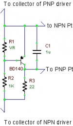
The modification is something I have seen on some Jap amps and is also described in Bob's book on Power Amp design ( page 291 Fig. 14.9 c ).
I used a resistance of 22 ohms but this is not final. The correct value will determine if it is over or under compensated.The important thing is that it does appear to mitigate the large drift problem. As expected, changing from a NPN to a PNP bias spreader did not appear to make any difference. I finally used a BD140 for further experiments.
So bias stability will be determined by a combination of , the location of the bias spreader transistor , the effective thermal resistance of the heat sink and the compensating resistor in the bias spreader.
Time to make a board with all the changes that have been made. Time to test it in stereo mode !
Spent several hours chopping tracks and wires and testing the end result.
So a modified bias spreader and it's transistor mounted close to the Darlington ( any one of the two ) seems to let the bias wander +/- 15 percent or less over a period of 2 hours . Ambient is about 32 deg C and there is no air flow around the fins oriented vertically. Bias was set to 100 mA after 30 minutes and then it was monitored.
The modification is something I have seen on some Jap amps and is also described in Bob's book on Power Amp design ( page 291 Fig. 14.9 c ).
I used a resistance of 22 ohms but this is not final. The correct value will determine if it is over or under compensated.The important thing is that it does appear to mitigate the large drift problem. As expected, changing from a NPN to a PNP bias spreader did not appear to make any difference. I finally used a BD140 for further experiments.
So bias stability will be determined by a combination of , the location of the bias spreader transistor , the effective thermal resistance of the heat sink and the compensating resistor in the bias spreader.
Time to make a board with all the changes that have been made. Time to test it in stereo mode !
Attachments
I ran the amp hard till the heat sink got so hot that you couldn't touch it for over a couple of seconds. That would make it over 55 Deg C at the fins.
I didn't measure it.
I shut off the music and the quiescent current dropped to normal very fast and stayed stable at about 110 mA even though the fins were still quite hot.
Next I ran the fan and the bias dropped only by about 10 % after about 20 minutes.
So this configuration is going to be stable at 100mA. No doubt about that.
Note that the current heat sink is really small.
Maybe I'll make an assisted output stage and bump up the supply voltage. Should be an interesting experiment. If it blows it should make a big bang I guess !
Good news!
Thank you.
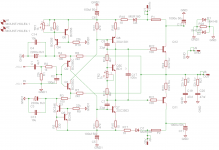
When you tested can you post the full schematic. Easier to imagine your mode if the whole schematic is posted. Specially to those people who follow the thread.. think about to build..
Also I think about to implement the CSS front end like LC.
I'm sure that would work much better than the noisy zeners. Of course the resistor values must be calculated.
According to LC that increase the amplifier performance a lot!
Do you have a scope, that would help alot if you could run some test to see if is oscillate or overshot.
For these project I do not want to invest, to buy a scope.
My hand tide because I do not own a scope.
Thank you one more time
Greetings
By the way if you exchange the emitter resistor to 0.33R that would cut back the dynamic and you will notice that in bass area to.
I would stick with the darlington power stage just double the transistors
Of course it need to be matched
wahab did posted a circuit several page back, that would help too much the darlingtons
You can test the discrete darlington (built up darlington from two BJT but when I tested I got very bad result compare to the BDWs)
Please do not forget alway do A-B test!
Greetings G
Thank you.
When you tested can you post the full schematic. Easier to imagine your mode if the whole schematic is posted. Specially to those people who follow the thread..
think about to build..Also I think about to implement the CSS front end like LC.
I'm sure that would work much better than the noisy zeners. Of course the resistor values must be calculated.
According to LC that increase the amplifier performance a lot!
Do you have a scope, that would help alot if you could run some test to see if is oscillate or overshot.
For these project I do not want to invest, to buy a scope.
My hand tide because I do not own a scope.
Thank you one more time
Greetings
By the way if you exchange the emitter resistor to 0.33R that would cut back the dynamic and you will notice that in bass area to.
I would stick with the darlington power stage just double the transistors
Of course it need to be matched
wahab did posted a circuit several page back, that would help too much the darlingtons
You can test the discrete darlington (built up darlington from two BJT but when I tested I got very bad result compare to the BDWs)
Please do not forget alway do A-B test!
Greetings G
Attachments
Last edited:
I have been monitoring the output with a scope. I did not see any RF problems until it clipped. But I will check this out with a stiffer supply soon. Have not yet looked at the square wave.
I have to get started on the stereo pcb now otherwise testing will get delayed. I'm off again after 2 weeks for a 10 day holiday!
I have been using the amp without an input capacitor all this while ! The cap will make a difference and I want to avoid using one. However I will check out different caps and post the listening results when the amp is in stereo mode.
Cheers.
The schematic is correct......................
I used a resistance of 22 ohms but this is not final. The correct value will determine if it is over or under compensated...................
It is an inverted version of D.Self's Vbe multiplier and importantly has the VR in the be side
It also has the D.Self resistor. Others have investigated this resistor and reported. The resistor is NOT a tempco. It is compoensation for changes in the current fed through from the VAS.
Very low VAS currents require a higher R value. I'd guess 22r suits VAS I of ~3mA.
15r suits ~ 7mA, 8r suits ~12mA.
You can check this (just the Multiplier with an adjustable CCS) on a plug board to find the optimum resistor for the current you plan to use.
The VAS transistor talks to it's complement.
In the quiescent state this "talking" is ONLY DC.
As soon as the VAS starts handling an audio signal, the "talking is an AC signal. The Vbe multiplier gets in the road and tries to interfere with the "talking". To minimise this interfering ability, you should connect the VAS to it's complement with a good audio capacitor. The AC passes through the cap. The multiplier is now left to try to maintain the correct bias voltage (DC) to keep the output bias current stable.
As I understood it , as the output power device draws more current the base current also increases. This is an additional current passing through the 22 ohms and hence reduces the voltage available from base to base of the output transistors ( = KxVbe of bias spreader - I( through 22 ohms) x 22 ) and hence the ability to reduce some current in the output stage as it's quiescent current tries to increase.
The 22 ohms does not sense temperature but reduces available dc bias voltage to the output devices as their current increases.
Bob has explained this in the book.
The 22 ohms does not sense temperature but reduces available dc bias voltage to the output devices as their current increases.
Bob has explained this in the book.
.......... the CSS front end like LC.
I'm sure that would work much better than the noisy zeners........
The zener noise is not a problem. It is attenuated by the large resistor and the nfb capacitor. Only very low frequencies down to dc will not be attenuated much. But in actual use the zener implementation is not noisy to the ear.
The amp sounds very good. Raising the bias to 100mA appears to make the mid range sound a bit smoother. Not sure if that is real . Will have to test again at lower bias. Getting tired of changing the bias so many times !
I don't see many posts on this thread. Looks like very few people are actually trying out this amp.
I forgot to mention that a regulated supply does help a lot. It keeps the voltages and current quite stable. However this can also be achieved by zener stabilisation of the supply to the small signal section of the amp. Providing a regulated supply for that stage would be ideal. Something like Ilimzin provided for his implementation of the LM7294 amp. Alternatively you could use separate taps on a transformer ( not everyone could do that easily ) .
However this amp with the TIP142/147 might not be safe with 100mA bias and +/-40 V supplies. At high volume and rising heat sink temp the power devices might hit the SOAR limit causing blue smoke. About +/-35 V seems to be OK. But at 100mA the heatsink must be much larger than what I have used. You might still need to monitor it till you are satisfied that it's playing within the safety limit under all conditions.
Considering how the amp sounds the LatFet is the safest bet but a discrete Darlington should be explored. That will be able to handle higher voltages and a 100 mA bias current and be thermally more stable.
Since it sounds so good it deserves further experimentation.
There is scope for lots of experimentation.
Now I need to try out the P3A to see how it compares !
Last edited:
Member
Joined 2009
Paid Member
I'm still following you with interest ! - I have a bunch of Sanken Darlingtons that might be well suited. However, I'm busy with another project which is better suited to the +/-50V power supply I have.
Most of all I'm interested in your experiments at stabilizing the bias. The topology does not favour stable bias and integrated Darlington devices are potentially more difficult to stabilize than a discrete so it's a difficult combination. The LatFET makes for such a good (thermal) solution ( e.g. in the VSSA) that I don't know yet if this Darlington output version is the right approach. I will continue to watch with interest.
Most of all I'm interested in your experiments at stabilizing the bias. The topology does not favour stable bias and integrated Darlington devices are potentially more difficult to stabilize than a discrete so it's a difficult combination. The LatFET makes for such a good (thermal) solution ( e.g. in the VSSA) that I don't know yet if this Darlington output version is the right approach. I will continue to watch with interest.
Hi Bigun,
As you also found out the LatFet version is stable.
The Darlington version becomes unstable at high bias ( 100mA and above) and if the heat sink is small. However with the modified bias spreader ( with the extra resistor in the collector of the bias Tr ) it is stable.
But there is still one catch. The dc bias does go up with high junction temp ( while playing loud music ) and could go up enough to kill the power transistors if operating on the borders of the SOA curve. Removing the music signal brings the bias down very quickly.So with +/-40 V and 100mA or more isn't exactly a safe thing to do. Certainly not with a small heatsink like mine but needs to be tested with a large sink. I'd say the TIP 142/147 might be safe if used with a max supply of +/- 36 V and bias current less than 100 mA. It sounds very good at 50 mA too.
To get to higher voltages and current you need to use Lat Fet's or discrete Darlingtons ! The discrete Darlington is really worth a try.
Last edited:
Member
Joined 2009
Paid Member
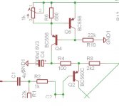
These is in my mind to compare with my old darlington.
Please take a look, opinion or and advise welcome on these circuit.
For the BD139 I will test a darlindton device after I power up the amp.
I do like the front of these amplifier all do several thing is different, have to be tested which is closer to my taste - like the feedback
Greetings G
Please take a look, opinion or and advise welcome on these circuit.
For the BD139 I will test a darlindton device after I power up the amp.
I do like the front of these amplifier all do several thing is different, have to be tested which is closer to my taste - like the feedback
Greetings G
Attachments
Hi G,
With the CCS the circuit is slightly better with respect to the output offset voltage and output bias current over a range of supply voltages.
However the PSRR appears poorer if you don't have a capacitance multiplier on the input stage supply line.
Remember to add the 22 ohms on the collector side of the bias spreader transistor. Note change of base connection on that side for the power transistor. Makes things more stable.
Times up ! I'm off again on the 16th and couldn't build the stereo board or the P3A ! Time really appears to be in short supply.
Blew the Darlingtons by using it at +/- 42 V and over 350 mA bias current. Didn't really do it intentionally but happened due to a set of goofs while fiddling with the board. But it did run for quite a while in that condition ! Not bad !
The stereo board will most likely use LatFet's . I have to choose between LatFet and Bipolar. Since I need a new power amp for my new coaxial OB speaker , the LatFet would be ideal. Bass will come from a sub.
Cheers.
- Home
- Amplifiers
- Solid State
- My first DIY amplifier 20 years a go