Member
Joined 2009
Paid Member
Wahab I didn't tested yet the mosfet amplifier, I really feel bad about that.
Just need those diodes ad trimmers to test that amp.
I was busy with some amplifier enclosures and other work at my free time but still I supposed to test that amp way back.
For the darlington which was modded by you only I made the PC boards yet.
I will test thoroughly that soon, for test I buy regular resisters at first.
I want to test if the stability of the amp get improved. If yes and the sound remain the same I do build that later with exotic parts.
Also I'm planing to test the mosfet version but not now.
First I must test of the Hitachi mosfet amplifier.. Only need to spend on that 10-15 bucks.
Probably next week I buy those diode and I put together the amp at least on a piece of plywood.
Greetings Gabor
Hi Gabor ,
To take time for a project has some advantages as often
we think about a few things quite lately when building a project ,
so stretching the things can only be profitable implementation wise.
About the project in this thread i would point a few things
that have been already said but are scatered in a lot of pages.
As you pointed it , the basic CCS allow far better DC stability
than the original version , rendering the input stage insensitive
to DC supply variations that otherwise would influence greatly
the quiescent current value.
Sanken darlingtons should provide not only better distorsion
figures but also higher power supply noise rejection due to
the absence of base-emitter resistors for the drivers ,
wich are implemented in Banat s replacements with a classic
double EF , those resistors are to be removed , as well as the
input stage dedicated VRs that not only are dangeourous if
trimmed to low values but have also the same drawback as in
the original schematic , that is highly variable input stage
current with all the nefarious consequences mentionned above.
On the use of laterals , Hitachi/Renesas are very good
but as you can see i did put a pair as it allow more
conductance and should largely compensate for the
lower current capability of thoses devices in respect of BJTs.
Lazycat claim that the fets he used for this design
sound better than the Hitachis is quite dubious and has
more to do with marketing behaviour than actual differences.
Exicon basicaly makes copies of the Renesas but with generaly
higher input capacitance and gate voltage thresholds , overall
they have not better specs at all , quite the contrary.
Overall , i find this design more balanced and reliable as well
as better compensated , the vssa has overshoots in the frequency
response at very high frequencies , at lest in the first versions ,
dont know how this was dealt with on following iterations.
On quiescent current stability experimented by Ashok ,
it appear that in the original design a PNP VBE multiplier
was used because it has lower junction voltage and as such
it seems the Iq is slightly more stable than with a NPN ,
i ll check again and post the results later.
Looking further the results of your experimentations
and how i could help if necessary , although it seems
to me that you have both all knowledge needed
to make the thing working reliably , neverless ,
i ll give a try to Bigun s proposition of using diodes
instead , a solution that i frequently used and wich
has worked very well.
Member
Joined 2009
Paid Member
Sanken darlingtons should provide not only better distorsion figures but also higher power supply noise rejection
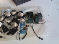
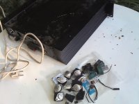
This is the type that I have, they look very nicely made. It would be handy to have spice models for these but alas they are not to be found.
Attachments
Last edited:
.........it appear that in the original design a PNP VBE multiplier
was used because it has lower junction voltage and as such
it seems the Iq is slightly more stable than with a NPN .......
It did occur to me that the original circuit used the PNP for better stability though I was not sure about it. However I did think of replacing the NPN that I used ( I have an excess of them ! ) with a PNP which entails some track cutting etc. Or maybe just do it point to point off the board.
After that I'll try the LatFet's that are just waiting to be tested. Assuming that all else works well the LatFET looks most interesting because it will be stable with regard to dc bias. I've been playing the existing circuit with reduced bias ( about 50 mA when idling) and find it works very well . It sounds very nice too !
It is however a busy week and I have to get some serious matters completed before the weekend. After that I'd be much more relaxed.
IF all goes well I'll be implementing a stereo board with 4 Power devices to each channel on a much larger heatsink. I still feel that I need to hear the amp in stereo to compare it properly against others.
Last edited:
As expected the data sheets do not show any difference between the PNP and NPN at a specific temperature. I would think that mounting the bias spreader on the power transistor might be the best bet. But just to complete the picture I will in any case try the PNP device also. It will delay my test with the LatFET's !
I think the approximate border at 100mA could just be due to reaction time of the bias spreader. Heat dissipation of the sink might be poorer at higher temperature and with the time delay associated with the bias spreader it causes the system to slowly approach a runaway condition. Maybe !
Another thing that might be a problem. The bias spreader when mounted on the power transistor will 'see' the power device through some thickness of plastic and that isn't a very good heat conductor. It might be better to place the BD139 upside down with the metal tab side facing up. Then place a small metal plate with mica insulation on it and then bolt it to the power transistor. Now the heat will flow up the screw into the metal plate and on to the metal tab of the bias spreader. This will reduce the temp differential between the two devices. Reaction time should be very low. Any thoughts ?
Last edited:
Member
Joined 2009
Paid Member
I don't think NPN or PNP is going to be a significant change wrt stability - I think the other approaches will be far more effective (i.e. degeneration, Hagerman bias spreader, NTC )
Edit - ignore that, I'm one post behind...
The bias spreader also has a sensitivity, not just how fast, but how much it changes the bias voltage for a specific change in temperature. I believe you can adjust it by changing the resistors around it - to change how much VAS current flows through the Vbe transistor and how much VAS current flows through the Vbe transistor bias string. You may need to make it more sensitive by increasing the impedance of the Vbe bas bias string (with same ratios).
Last edited:
wahab
Thank you for your help I got to these project and to the mosfet amplifier also.
I'm at the door step to test that, also I'll go ahead to test the modded verison of these Darlington circuit.
About the Exicon LatFet
I tested the Hitachi vs. Exicon in my DIY ProFet amplifier.
I do preffer the Exicon in that circuit.
But again that a Class A amplifier similar to the N Pass F5 with LatFet.
I do have no interest to promote the Exicon in any way!
I'm happy you still follow these thread, we need your help, advise here.")
Bigun
I hope you"r serious to test those Sanken Darlingtons soon.
I invested so much to these project over the years I do not want to keep spending just to get more experince..
If I know those or other Sanken I can use sucsessfully at these project (even if I get just a little improvement, stability) definately I would invest, but again....
banat
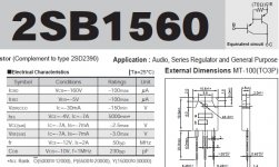
Those Toshiba devices one of my favorite power transistors.
It is a same no longer avaleble, just some China made Ebay stuff.
Greetings G
Thank you for your help I got to these project and to the mosfet amplifier also.
I'm at the door step to test that, also I'll go ahead to test the modded verison of these Darlington circuit.
About the Exicon LatFet
I tested the Hitachi vs. Exicon in my DIY ProFet amplifier.
I do preffer the Exicon in that circuit.
But again that a Class A amplifier similar to the N Pass F5 with LatFet.
I do have no interest to promote the Exicon in any way!
I'm happy you still follow these thread, we need your help, advise here.
Bigun
I hope you"r serious to test those Sanken Darlingtons soon.
I invested so much to these project over the years I do not want to keep spending just to get more experince..
If I know those or other Sanken I can use sucsessfully at these project (even if I get just a little improvement, stability) definately I would invest, but again....
banat
Those Toshiba devices one of my favorite power transistors.
It is a same no longer avaleble, just some China made Ebay stuff.
Greetings G
Last edited:
wahab do you think it would be worth to give a try to vertical mosfet like Toshiba 2SJ201/2SK1530 in these circuit?
The reason for ask I have a set for a stereo, I purchased from the forum GB to a lower power F5 project way back a few years ago, now it look like that project will not going to happen.
Because those are precision matched it cost me a lot, for that reason isn't worth to just re-sell them or keep in my box among the rest of the semiconductors.
I know it would be need to take care the different tempco, any other modification?
It would be great to find a good use for those higher power mosfet.
Another reason I have several LatFet project already.
For these circuit with LatFet I designed the PC board layout but not the PC boards yet.
I could modify the layout in case if it would be worth to give a try to those Toshiba mosfet.
Greetings G
Hi G,
I look upon the schematic on post 336 with japanese transistor...what is the bias for this amp? i have all the transistors...did it sound horible if using original transistor?
greetings,
Josh
I can not comment that circuit with the original semiconductors.
I never built it or heard that
I built something similar with total different semiconductors, that sounded very bad.
But again when we start to use transistors whatever we just has at home we very likely end up with a average sound if not a bad sounding amp like me.
Greetings Gabor
I have some 2SK1530/2SJ201 bought for a different project. They were far more expensive than the 2SK1058/2SJ162 .
The gate source voltage required to turn them on is I think higher ( 1.6 V )than the Hitachi's ( 0.6 V ) but lower than the ( about 4 V?) of the IRF hexfet's.
Your circuit will probably clip a bit earlier than the Hitachi's. Apart from that I don't know of any other reason why you can't use it. It is physically larger than the Hitachi devices.
Vds sat is also high at about 4 V at 5 Amps. So for a certain supply voltage you will get less unclipped output than using bipolars. But this is similar to the Hitachi's.
Are the 2SK1530/2SJ201 still in production ?
Edit: OK just found that they are no longer in production !
Last edited:
This is the type that I have, they look very nicely made. It would be handy to have spice models for these but alas they are not to be found.
Theses are perfects for the purpose but be carefull
to limit the PSU voltage to safe values if you re using
only one pair of devices.
I ll also do a try with Sankens MP1620/MN2488 ,almost
the same as theses ones safe for power that is 150W ,
i ll set the PSU to +-24V for one pair.
wahab do you think it would be worth to give a try to vertical mosfet like Toshiba 2SJ201/2SK1530 in these circuit?
The reason for ask I have a set for a stereo, I purchased from the forum GB to a lower power F5 project way back a few years ago, now it look like that project will not going to happen.
Because those are precision matched it cost me a lot, for that reason isn't worth to just re-sell them or keep in my box among the rest of the semiconductors.
I know it would be need to take care the different tempco, any other modification?
It would be great to find a good use for those higher power mosfet.
Another reason I have several LatFet project already.
For these circuit with LatFet I designed the PC board layout but not the PC boards yet.
I could modify the layout in case if it would be worth to give a try to those Toshiba mosfet.
Greetings G
Hi Gabor ,
Theses are excellent devices , many people in this forum
prefer them over the Hitachi s due to their higher conductance
but contrary to the laterals they have not a negative temperature
coefficient , meaning that they need a thermal compensation ,
either using an adequate VBE multiplier or more simply two
or three diodes coupled with a trimmer that is parraleled
with one of the diodes , i ll take a look with the simulator
to check a good arrangement.
On the NS application note they have slightly less distorsion
than the laterals but nothing that could make a difference ,
we re talking of 0.008% instead of 0.006%.
I d like to point that there s extremely low returns when
using expensive devices with the Profet , F5 and other low
feedback amplifiers wich mandate very high quality transistors
with careful matching to reach quality levels that are still
sub par compared to high feedback designs.
For the record , i think that this amp is better than both
F5 and Profet due to its higher feedback.
It did occur to me that the original circuit used the PNP for better stability though I was not sure about it. However I did think of replacing the NPN that I used ( I have an excess of them ! ) with a PNP which entails some track cutting etc. Or maybe just do it point to point off the board.
Hi Ashok ,
Well , in the simulator the PNP has 30mV lower VBE
than the NPN , thermal stabilty is at odd using the same
circuit , with the PNP giving slight overcompensation
while the NPN is the other way around.
In principle the VBE multiplier device should have low VCEsat
and a high beta wich is not the case of most TO126
transistors that are used not for their electrical qualities
but rather for the ease of mounting , that s one thing
where really the DIYers have settled irrationaly but
it s true that devices that are mechanicaly adequate
and still poviding the good caracteristics are not produced ,
safe by SANKEN and surely thatr it s neither cheap
nor easy to find , personaly i never got a single one.
Attachments
........In principle the VBE multiplier device should have low VCEsat and a high beta wich is not the case of most TO126.....
I don't understand the Vsat requirement. As it is the Vsat is just about 50 mV at the currents we use in a Vas stage. Why would this be a problem ? The Vce ( dc ) of the BD139/140 would be at least 1.2 V or more under normal operating conditions .
Last edited:
Hi Gabor ,
Theses are excellent devices , many people in this forum
prefer them over the Hitachi s due to their higher conductance
but contrary to the laterals they have not a negative temperature
coefficient , meaning that they need a thermal compensation ,
either using an adequate VBE multiplier or more simply two
or three diodes coupled with a trimmer that is parraleled
with one of the diodes , i ll take a look with the simulator
to check a good arrangement.
On the NS application note they have slightly less distorsion
than the laterals but nothing that could make a difference ,
we re talking of 0.008% instead of 0.006%.
I d like to point that there s extremely low returns when
using expensive devices with the Profet , F5 and other low
feedback amplifiers wich mandate very high quality transistors
with careful matching to reach quality levels that are still
sub par compared to high feedback designs.
For the record , i think that this amp is better than both
F5 and Profet due to its higher feedback.
Hello
Thank you wahab!
That is a good news. It would be wiser if I could use those Toshiba here than the F5..
Specially if we could adopt the circuit to use the Toshibas close to their potential.
I mean not just to be used up or be saved..
I have a lot of those cheap HexFet for Pass amplifier in case but I lost the interest for the regular F5.
I built the ProFet with $4 & $7PC Caddock resistors, after I built two more channel more, altogether 4 channel.
At first I did like the sound of that amp (was tested in a small room) until I rebuilt the Darlington and I made A-B comparison.
The Darlington was on hold for years until I found acceptable components to replace some of those old devices no longer available.
Now as good at least than at first when the amp was developed if not better but still I want to test a few think before the final rebuild.
I agree with you on that these amplifier sound way better than the ProFet.
So much better now I think it was a huge waste of money that investment (the ProFet) specially those expensive resisters..
I think the F5 is somewhere at the same level or so. I no longer believe that amp will deserve to use up those Toshiba devices..
Ashok
That mosfet still available many stores.
Many ASPEN amplifier use those Toshiba devices with excellent result.
Greetings Gabor
Hello
Thank you wahab!
That is a good news. It would be wiser if I could use those Toshiba here than the F5..
Specially if we could adopt the circuit to use the Toshibas close to their potential.
I have a lot of those cheap HexFet for Pass amplifier in case but I lost the interest for the regular F5.
I built the ProFet with $4 & $7PC Caddock resistors, after I built two more channel more, altogether 4 channel.
At first I did like the sound of that amp (was tested in a small room) until I rebuilt the Darlington and I made A-B comparison.
The Darlington was on hold for years until I found acceptable components to replace some of those old devices no longer available.
Now as good at least than at first when the amp was developed if not better but still I want to test a few think before the final rebuild.
I agree with you on that these amplifier sound way better than the ProFet.
So much better now I think it was a huge waste of money that investment (the ProFet) specially those expensive resisters..
I think the F5 is somewhere at the same level or so. I no longer believe that amp will deserve to use up those Toshiba devices..
Greetings Gabor
Hi Gabor ,
I m sure at 100% that thoses resistors bring absolutely nothing ,
moreover with F5/Profet whose caracteristics are only transistors
dependent , so dont waste money on devices that are hyped
and wich have far less influence than the layout.
If you want to use the toshibas you can use the VBE multiplier
of the darlington version although a resistor will have to be adapted ,
likely that the one in serial with the trimmer should be slightly reduced
to allow for a convenient current range.
Once Ashok or Bigun try the Sankens we ll have an idea
of how they perform , i ll also use thoses devices to check
this amp s eventual bugs.
I don't understand the Vsat requirement. As it is the Vsat is just about 50 mV at the currents we use in a Vas stage. Why would this be a problem ? The Vce ( dc ) of the BD139/140 would be at least 1.2 V or more under normal operating conditions .
I guess that low a VCEsat transistor has also low VBE
and idealy for the multiplier to work perfectly it should
have 0V VBE and very high beta such that the voltage
drop due to the base current doesnt vary much with temp.
Member
Joined 2009
Paid Member
Bigun
I hope you"r serious to test those Sanken Darlingtons soon.
I invested so much to these project over the years I do not want to keep spending just to get more experince..
If I know those or other Sanken I can use sucsessfully at these project (even if I get just a little improvement, stability) definately I would invest, but again....
I thought the problem was that if I build it, then I can not compare with your amplifier because I don't have your amplifier. You sound like you have too many projects - but perhaps I should send you a pair of devices to try out if you can do it soon. On the other hand, I think you live only a hour or so from me and I could bring my amplifier to your ears - except I can't build anything until August due to my day-job and family commitments during July (I could plan a pcb though...)
I d like to point that there s extremely low returns when
using expensive devices with the Profet , F5 and other low
feedback amplifiers wich mandate very high quality transistors
with careful matching to reach quality levels that are still
sub par compared to high feedback designs.
For the record , i think that this amp is better than both
F5 and Profet due to its higher feedback..
It isn't the topic of this thread - but I'm not so convinced that high feedback is always good. If it is implemented well it can be of great value, but I see many people giving up high feedback around the output, using only around the input stage and using less feedback around the output power stage. I think there is something to learn and explore in this.
I think the output bias is sensitive to the input stage dc conditions. This becomes more stable if the input and driver stage uses a regulated supply. Alternatively the input stage can have a zener stabilised supply as Wahab has shown in one implementation. This needs to be checked before trying any other devices. Maybe I can do it on my current board.
I realised this when I was checking the bias this morning and couldn't get the levels I wanted. I then noticed that the mains voltage was very low and the supply fell to +/-34 V when the amp stopped responding to the bias control. A quick simulation revealed the sensitivity to the supply voltage.
I realised this when I was checking the bias this morning and couldn't get the levels I wanted. I then noticed that the mains voltage was very low and the supply fell to +/-34 V when the amp stopped responding to the bias control. A quick simulation revealed the sensitivity to the supply voltage.
I think the output bias is sensitive to the input stage dc conditions. This becomes more stable if the input and driver stage uses a regulated supply. Alternatively the input stage can have a zener stabilised supply as Wahab has shown in one implementation. This needs to be checked before trying any other devices. Maybe I can do it on my current board.
I realised this when I was checking the bias this morning and couldn't get the levels I wanted. I then noticed that the mains voltage was very low and the supply fell to +/-34 V when the amp stopped responding to the bias control. A quick simulation revealed the sensitivity to the supply voltage.
Wich schematic are you using.?.
Without CCS the input stage current will be about
proportional to the supply voltage , increasing the VAS
current by the same way and thus rendering the quiescent
current highly supply voltage dependant , as the voltage
at the VAS base and thus emitter will increase accordingly
with increasing voltages.
The CCSs at the input will render any stabilisation useless
with VAS current that will vary only with temperature
at a rate of 0.2%/°C for the schematic using darlingtons
and CCSs.
- Home
- Amplifiers
- Solid State
- My first DIY amplifier 20 years a go