CM Discussion
Lineup
The 15W/Ch Amplifier and Preamp use basically similar circuitry except for the output stage, and a few other minor changes. The 15W /Ch has a 4.7uF polyprop input capacitor, and doesn't currently use an Offset Corrector.
The version used by vhfman has a CFP VAS, and uses the diode in the CM method, and the value of the VAS emitter resistor is slightly adjusted to achieve a similar balance, and a fairly similar performance.
SandyK
An externally hosted image should be here but it was not working when we last tested it.
An externally hosted image should be here but it was not working when we last tested it.
Speaking of "blameless"heres the guinea pig. These are the 3rd
& 4th amps, and for these I added the buffered widlar
and schottky diode w/ trimpot. As I didnt want to make new boards all mods are smd underneath.
As far as self amp being "bland" , I listened to this one's
driver stage with headphones (like in pix) ..standard CM
..buffered mirror, and with all mods.
Standard sounds noticebly better than my HT receiver,
with either or both of the 2 mods "eerie" is the only
word for it.
How good "eerie" sounds is dependant on the VAS current,
I've found 14ma for the VAS is the ideal.(adjustable current
source).

Strange about the 3 tranny mirror , the offset trim has
a much wider "zero range" almost like auto offset comp.
measuring the LTP only microamps of difference.
OS

for those new to I sources/mirrors heres a web page that explains the basic types of current mirrors and LTPs with current mirrors.
http://www.zen118213.zen.co.uk/RFIC_Subcircuits_Page.htm
http://www.zen118213.zen.co.uk/RFIC_Subcircuits_Page.htm
eerie could be good or bad
Eerie is the amp that haunts your dreams because you can't wait
to get up in the morning to listen to it.
Is not that VAS cascoded?? (as would say yoda)The version used by vhfman has a CFP VAS
Os
Hi Sandyk, I have no problem with blameless type amps, I have a 15 year old clone although I wouldnt call it a clone as its more based on JLH s design ideas that sounds comparable to 12 000 pound electrocompaniet monoblocks I have. The biggest changes Ive made with the blameless is compensation and fine detail into component selection and small tweaks into current sources and mirrors. Balancing ltps which is beneficial has always been a small headache which is why my interest in this thread. Its beneficial with other topologies too. I wasnt thinking of the CM diode trick, I dont think Id use that although sims tells me it could be of some value. The idea of all the current mirrors is to balance the 2 halves of the ltp while getting the added advantages that CM bring. By better balancing the CM youll get the better balance in the LTP. Try simming the combination I proposed and youll find that you get much closer ltp balance.
Lineup dont worry this is not a groupthink, its actually quite the opposite, read carefully what groupthink entails and how its characterised. True there are some threads where this can be seen but here people are giving their own innovative ideas and experiences which is the quite the opposite. Nobody here has so far put a stance and the others followed it without challange or investigation.
Lineup dont worry this is not a groupthink, its actually quite the opposite, read carefully what groupthink entails and how its characterised. True there are some threads where this can be seen but here people are giving their own innovative ideas and experiences which is the quite the opposite. Nobody here has so far put a stance and the others followed it without challange or investigation.
CM Discussion
homemodder
There are many ways to get a much closer balance. What I am saying is that since 1987 I have found with many different amplifiers, using different topologies,i.e. with or without Current Mirrors, that if the LTP transistors are selected for a close balance in HFE, and a very close balance in VBE, that the sound quality markedly improves when the voltage difference between these well matched transistor's collectors is within +-5mV. I agree that this doesn't sound plausible, but it has been verified by several DIYAudio members in both U.K. and Australia, as well as one from India who was open minded enough to try the suggestion. The member from India also commented that he was then able to hear the noise floor of some CDs.
SandyK
Many thanks also, to AKSA for having such an open mind, and daring to post the original diode suggestion.
Many thanks also, to AKSA for having such an open mind, and daring to post the original diode suggestion
Yeah , without aksa I would have to settle for plain.
(not that it is bad)
that if the LTP transistors are selected for a close balance in HFE, and a very close balance in VBE, that the sound quality markedly improves when the voltage difference between these well matched transistor's collectors is within +-5mV.
Now I have a hard time unbalancing the diff. <1mv
Lineup dont worry this is not a groupthink, its actually quite the opposite, read carefully what groupthink entails and how its characterised. True there are some threads where this can be seen but here people are giving their own innovative ideas and experiences which is the quite the opposite. Nobody here has so far put a stance and the others followed it without challange or investigation.
Maybe because it really does work.
OS
CM Discussion
quote:
The version used by vhfman has a CFP VAS
Is not that VAS cascoded?? (as would say yoda)
Os"
The original design from Silicon Chip was cascoded.
Vhfman does indeed use a CFP in the VAS, AND the Output Stage. It took a bit of taming, but works very well.
SandyK
quote:
The version used by vhfman has a CFP VAS
Is not that VAS cascoded?? (as would say yoda)
Os"
The original design from Silicon Chip was cascoded.
Vhfman does indeed use a CFP in the VAS, AND the Output Stage. It took a bit of taming, but works very well.
SandyK
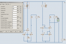
One comparing sim test of current mirrors.
I will refer to the left one as 'Glen mirror'
and the right one is 'Jam mirror'.
The condition for this compare is:
1000 uA, modulated with +-100uA 10 kHz
Output is at 1.3 Volt, as for a darlington VAS.
We can not say one type of mirror is best.
We have to consider the circuit.
Like if the output is taken at 0.65, 1.30 or much higher voltage.
The Glen mirror performs a bit better here.
One natural explanation is that U4/U5 both work at 1.30 Volt level
while U6/U7 only works at 0.65 Volt level.
I say, in compare with other options, the Jam 4 Transistors mirror
is a very good mirror alternative.
Surely one of the best
How much current in U1, set by resistor R3 will effect the distortion.
in this case the optimal value is ~1200 Ohm, which gives a current like 500 uA in U1.
This is 50% of 1000 uA, in U4/U5.
I do not know if this 50% is some general ratio. It does not have to be.
It may be, that at ~500 uA the U1 will start to perform well.
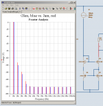
I post the Fast Fourier Analys in next post.
I will refer to the left one as 'Glen mirror'
and the right one is 'Jam mirror'.
The condition for this compare is:
1000 uA, modulated with +-100uA 10 kHz
Output is at 1.3 Volt, as for a darlington VAS.
We can not say one type of mirror is best.
We have to consider the circuit.
Like if the output is taken at 0.65, 1.30 or much higher voltage.
The Glen mirror performs a bit better here.
One natural explanation is that U4/U5 both work at 1.30 Volt level
while U6/U7 only works at 0.65 Volt level.
I say, in compare with other options, the Jam 4 Transistors mirror
is a very good mirror alternative.
Surely one of the best
How much current in U1, set by resistor R3 will effect the distortion.
in this case the optimal value is ~1200 Ohm, which gives a current like 500 uA in U1.
This is 50% of 1000 uA, in U4/U5.
I do not know if this 50% is some general ratio. It does not have to be.
It may be, that at ~500 uA the U1 will start to perform well.
I post the Fast Fourier Analys in next post.
Attachments
I haven't tried the "jam" mirror yet .. no more SMD's left.
I like to see the sim verifying what I hear.. could anybody
SIM a unbalanced degeneration on the LTP.(auto balance effect)
The wide offset range is most curious..
Line up .. try hooking collector of U1 to other rail instead of ground
(use very high Vceo tranny) w/ 2.2k res. cancels ripple (PSRR)
2 birds w/ one stone..
PS .. I,m "relistening" to floyd now,never heard it like this on any
audio I bought in a store. thanks DIYaudio..
OS
I like to see the sim verifying what I hear..
could anybodySIM a unbalanced degeneration on the LTP.(auto balance effect)
The wide offset range is most curious..
Line up .. try hooking collector of U1 to other rail instead of ground
(use very high Vceo tranny) w/ 2.2k res. cancels ripple (PSRR)
2 birds w/ one stone..
PS .. I,m "relistening" to floyd now,never heard it like this on any
audio I bought in a store. thanks DIYaudio..
OS
ostripper said:Eerie is the amp that haunts your dreams because you can't wait
to get up in the morning to listen to it.
Maybe I'll call my next amplifier Woody.
Nelson Pass said:
Maybe I'll call my next amplifier Woody.
Hi Nelson
Perhaps you could call it FETtucine ? You might wake up awfully hungry though ?
Sorry about that!
SandyK
CM Discussion
"Hey , how'd you guys know .. I'm going to put it in a wood case,
(no chassis yet ,one ordered for XMAS.)"
ostripper
I hope that the wooden case doesn't have any screws ? It must be glued together !
Below is from RockGrotto forum, and was posted by Richard Dunne (Nenevalleyaudio) I don't think we better go any further with this one though !
Re: NVA-AP10H
« Reply #58 on Oct 21, 2008, 12:18am »
--------------------------------------------------------------------------------
Oct 20, 2008, 8:56pm, headphonecat wrote: hi everyone, and hello Richard i was just wandering if you could outline the theory or background of the perspex case for the NVA as i have found an improvement in sonics when it was removed from atop a Cyrus cd8x to its side on its own mini support (also a piece of perspex). Due you think the perceived improvement could be due to simply increasing the distance of the unit from any metal boxes filled with electronics? it would be interesting to have some theories to help with support design experimentation as my phyisics is a little rusty! Any books on the subject for our own reading would be great too!javascript:add("%20")
It is all to do with field effects. There are many types of field - electro magnetic - plain magnetic - electrostatic - natural static etc. Some influence electronic circuits, most are created by electronic circuits. So the problem is you have fields created inside the unit and outside the unit. You have two ways to deal with these problems, either do everything you can to block these fields or do everything you can to allow these fields to flow unimpeded. We follow the latter. Both have problems and it is a compromise decision as with most things in audio. Fields don't disappear if you block them, ok you block the external but the internal bounces around reflected into other parts of the circuits and then you not only get the field influence you get phase effects from the field depending on the field decay. NVA cases allow that internal field out so the circuit is not interfered with, but the downside is external field can get in, so positioning and what it is next to will influenced it.
You pays yer money and you takes yer choice, there is no in between compromise as it leaves you with the worst of both worlds, our choice our compromise. You will find that it can sit on some things and not on others the Cyrus must be one of the latter.
There are no books there are your ears and hands on experience.
"Hey , how'd you guys know .. I'm going to put it in a wood case,
(no chassis yet ,one ordered for XMAS.)"
ostripper
I hope that the wooden case doesn't have any screws ? It must be glued together !
Below is from RockGrotto forum, and was posted by Richard Dunne (Nenevalleyaudio) I don't think we better go any further with this one though !
Re: NVA-AP10H
« Reply #58 on Oct 21, 2008, 12:18am »
--------------------------------------------------------------------------------
Oct 20, 2008, 8:56pm, headphonecat wrote: hi everyone, and hello Richard i was just wandering if you could outline the theory or background of the perspex case for the NVA as i have found an improvement in sonics when it was removed from atop a Cyrus cd8x to its side on its own mini support (also a piece of perspex). Due you think the perceived improvement could be due to simply increasing the distance of the unit from any metal boxes filled with electronics? it would be interesting to have some theories to help with support design experimentation as my phyisics is a little rusty! Any books on the subject for our own reading would be great too!javascript:add("%20
") It is all to do with field effects. There are many types of field - electro magnetic - plain magnetic - electrostatic - natural static etc. Some influence electronic circuits, most are created by electronic circuits. So the problem is you have fields created inside the unit and outside the unit. You have two ways to deal with these problems, either do everything you can to block these fields or do everything you can to allow these fields to flow unimpeded. We follow the latter. Both have problems and it is a compromise decision as with most things in audio. Fields don't disappear if you block them, ok you block the external but the internal bounces around reflected into other parts of the circuits and then you not only get the field influence you get phase effects from the field depending on the field decay. NVA cases allow that internal field out so the circuit is not interfered with, but the downside is external field can get in, so positioning and what it is next to will influenced it.
You pays yer money and you takes yer choice, there is no in between compromise as it leaves you with the worst of both worlds, our choice our compromise. You will find that it can sit on some things and not on others the Cyrus must be one of the latter.
There are no books there are your ears and hands on experience.
Move over Wilson and Widlar!
Lineup,
I have to say that I am proud to have a mirror named after me.
Thanks for all the hard work.............I have used both mirrors with great success.
I would like to know if anyone has used the cascoded Glen Mirror which I have posted.........here it is again......
The Cascoded Glen Mirror.
Lineup,
I have to say that I am proud to have a mirror named after me.
Thanks for all the hard work.............I have used both mirrors with great success.
I would like to know if anyone has used the cascoded Glen Mirror which I have posted.........here it is again......
The Cascoded Glen Mirror.
Attachments
- Home
- Amplifiers
- Solid State
- Current Mirror Discussion