Hi diyaudio members!
I'm attempting to build David White's Mos100 amplifier.
http://www.wnaudio.com/amos100.pdf (details and schematic)
I have a mono stage ready, but it's oscillating.
I have connected a 40W bulb in series with the AC line, the VR is turned fully anti-clockwise (0 ohm).
If I power it up with a dummy load it draws about 20 mA in the positive supply line.
The output measures 0V AC/0V DC.
But, if I try to adjust the bias, as soon as the VR is turned to the point where the amp will start drawing more then 20mA it will start to oscillate even if I turn the VR back to 0 ohm. The output reads 0VDC/2.7V AC.
Using a speaker as the load the same thing happens as I power it up (the amp appears to be stable, no output and draws ~20mA), but as soon as I touch/tap the speaker, I get the same result. 2.7V AC in the output, drawing about 350mA in the positive supply line.
I suppose the oscillation is in the inaudible frequency range.
Other then that, the amp appears to be working, of course I get the inter-modulation distortion since I can't set the bias.
I also tried running it without the 40W bulb in series with the AC line.
I didn't have to tap the speaker, or to touch the VR in order to get it to oscillate. I didn't have a chance to check how much current it was drawing or the output, since the 10 ohm 3W resistor in the zobel network was giving off smoke so I just unplugged it.
I used the same parts as in the schematic except for the output mosfets (I used BUZ901/BUZ906) and instead of the 2N 3704 I used a BC 337.
Unfortunately I don't have a scope, and I don't know anyone who does...
Any help would be greatly appreciated!
Tibi.
im not familiar with this amp, but some quick things to check for
- zobel network (if used). check resistor and cap with meter and verify good (low R) ground connection to zobel.
- output coil and resistor (if used). doesn't seem suspect though since you are using a dummy load.
- check all components, circuit traces and grounds in the nfb circuit. same for the input network infront of the LTP.
- check decoupling caps to make sure RF or other high freq junk isn't being injected into the rails.
- miller cap. if defective or wrong value or installed improper it will push the P2 cutoff point higher.
lineup said:
The first I should try
is increase C14 to 47pf and 100 pF is needed
I would try removing C14. I had a similar oscillation problem and that was the cure.
lineup said:I assume you have the R22, C18 filter attached.
The first I should try
is increase C14 to 47pf and 100 pF is needed
If this does not help I would add C15.
Maybe try something like 100-470 pF
Yes the R22 and C18 filter is attached, R22 gets pretty hot when it's oscillating.
Thanks for the tips, I'll try increasing C14, I don't have a 47pf capacitor handy, for testing I suppose I can use 2 or 3 22p caps in parallel.
lineup said:Also the PCB can matter.
I would put R1 and R2 and R5 close to input pins
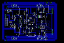
I'm afraid that the main cause here is the PCB itself, I couldn't find the original PCB, so I designed my own, but I don't have much experience with designing PCBs.
I've attached the PCB. Let me know what you thing please.
P.S. The OPamp I used is an OPA604 not TL... as in the PCB.
Attachments
ballai.tibi said:
I'll try increasing C14, I don't have a 47pf capacitor handy, for testing I suppose I can use 2 or 3 22p caps in parallel.
Seriously, try it first without it.
You won't miss that filter anyway.
I wouldn't count on it being poor board design. I've had stuff running stable on pieces of plywood.
gain said:im not familiar with this amp, but some quick things to check for
- zobel network (if used). check resistor and cap with meter and verify good (low R) ground connection to zobel.
- output coil and resistor (if used). doesn't seem suspect though since you are using a dummy load.
- check all components, circuit traces and grounds in the nfb circuit. same for the input network infront of the LTP.
- check decoupling caps to make sure RF or other high freq junk isn't being injected into the rails.
- miller cap. if defective or wrong value or installed improper it will push the P2 cutoff point higher.
thanks for the tips.
I just put the amp together yesterday so I don't think it's component failure, however I wouldn't rule out that some components although new could be defective.
- The zobel network reads a ~10ohm resistance to the ground so that seems to be in order.
- Not sure what I should check for in the output coil/resistor... I wound that myself, 17 turns of 0.9mm enameled copper wire on a 10 ohm 3W resistor.
- I re-checked the components and circuit traces, everything seems to be in order
- Sorry, but I'm not sure which capacitor is the miller cap in the schematic, would that be C4? between the input signal and the ground?
thanks.
MJL21193 said:
Seriously, try it first without it.
You won't miss that filter anyway.
I wouldn't count on it being poor board design. I've had stuff running stable on pieces of plywood.
thanks for the suggestion MJL21193. however I've already tried that even before lineup suggested increasing the value, but it didn't solve the problem.
With 3x22pf as C14 though the amp appears to be stable with no input signal, I was able to remove the 40W bulb from the ac line and set the bias.
If I feed it an input signal it works, no distortion, no oscillation as long as the output voltage is under 1.5 volts, as I increase the input signal it starts oscillating again.
Even so, I feel that we've made some progress. just not quite "there" yet.
")
I'll have to get some caps in the 100-470pf range tomorrow to try and add C15 to see if that makes a difference.
Sorry if my reply's appear to be out of order, since I'm a new member I have to wait for each of them to be approved by a moderator.
Just had a quick look at the schematics. This outputstage has got voltage gain, its going to be complicated getting this amp stable, messing that much around with c14 is not the way to go, maybe go 47pf. Agree with lineup, put some capacitance on c15 and mabe try decreasing R19 a bit to lower the gain, you dont need that much. What transistors are you using for TR4 and 5, theyll have to be pretty fast like the ones shown on schematic.
Hi all,
Based on my experience with Lateral Power Mosfet on amplifiers, before to do all said above ( regards for all ) I would increase the values of gate resistors. Mainly because two reasons:
1) Lateral mosfets behavies on diferent aproach from vertical ( most commom ) mosfets like IRF´s;
2) Exicon lateral power mosfet ( used in this case ) has diferent capacitances values from Hitachi Lateral power mosfet.
Once time I had to increase the gates resistors to 3k3 to stop oscilation on a Marshall guitar amplifier model when I insatalled Exicon mosfet ( original parts was Hitachi lateral mosfet ).
Try 1k5 to 3k3 to test.
If it don´t stop the oscilation , do what was said before.
Regards,
-Ed
c15 might be part of the problem. if i'm reading the schematic right, you have an inversion with gain between the driver emitters and the mosfet drains. if the phase shift from the mosfet Cdg (drain-gate capacitance) and c15 add up to 180 degrees, and the inversion is 180 degrees, you have a total of 360 degrees phase shift at some RF frequency, and you've just made an oscillator. nested feedback loops, especially ones with caps can be problematic.
homemodder said:Just had a quick look at the schematics. This outputstage has got voltage gain, its going to be complicated getting this amp stable, messing that much around with c14 is not the way to go, maybe go 47pf. Agree with lineup, put some capacitance on c15 and mabe try decreasing R19 a bit to lower the gain, you dont need that much. What transistors are you using for TR4 and 5, theyll have to be pretty fast like the ones shown on schematic.
I'll have to wait until tomorrow to get some new caps for C15
Tr4 and Tr5 are 2SC2911 & 2SA1209
What value would you recommend I should try for R19?
thanks.
Ok, here's what I've tried so far and the results:
I've tried increasing the value of the mosfet gate resistors. my first attempt was 200 ohm, didn't seem to make any difference, I tried 1.5k and 3.3k, neither of them made a difference.
I have added a 470pf cap as C15, now I can remove C14 from the nfb circuit as the amp is stable with no input signal even without it. (however I left a 47pf cap as C14)
I've tried reducing the value of R19 to 1.5kohm and 1kohm, besides reducing the gain, it didn't seem to make a difference.
The amp works as long as the input signal is weak, as I increase it I can't hear any sound, the amp starts drawing ~1.2-1.5 amps in the positive supply line, the AC output is off the scale (50V) and there is a 2V DC on the output as well.
If I test it with a 40W light bulb in series with the AC line, the result is similar the difference being is I can still hear the music but I also hear a loud "pop" every 1.5-2 seconds and that's when it's drawing more current.
another thing i've noticed in the past, and later found an app note that confirmed what i already suspected.....
an op amp that's too fast for the VAS and output stage will cause an amp to oscillate. i later found more info about this at www.linear.com. do a search for app note AN-47.
one other thing you might try...... i noticed C15 in the schematic s marked "OMIT".
remove C15.
an op amp that's too fast for the VAS and output stage will cause an amp to oscillate. i later found more info about this at www.linear.com. do a search for app note AN-47.
one other thing you might try...... i noticed C15 in the schematic s marked "OMIT".
remove C15.
unclejed613 said:another thing i've noticed in the past, and later found an app note that confirmed what i already suspected.....
an op amp that's too fast for the VAS and output stage will cause an amp to oscillate. i later found more info about this at www.linear.com. do a search for app note AN-47.
one other thing you might try...... i noticed C15 in the schematic s marked "OMIT".
remove C15.
Yeah, I've heard of that before, however quite a few MOS100 amps were made with the OPA604 op amps, and the driver transistors and mosfets are both high speed, so I don't think that would be the source of the problem.
I only added C15 today to stabilize the amp with no input signal. It's stable with no signal either when C15 is there (100pf or 470pf both work) or C14 is increased to over 60pf
OPA604 is a bit faster than OPA134
What I have managed to understand
is that OPA134 is less prone to oscillations than OPA604.
I have read about cases when OPA2604 has been unstable.
I would make a try to replace with OPA134.
They are very similar in data, besides the slewrate.
Of course the main cause of oscillation can be output stage
and if so, then a replacement of OPAMP wont help.
Your layout doesnt seem to be bad, personally I would never build this amp, trying to get that much gain from a output stage is looking for trouble but I have chatted though long ago to some diyers that built it successfully. I can tell you that that outputstage sounds very good indeed, basically a mosfet CFP with gain. Ive used it sucessfully but not with so much gain.
UncleJed and Lineup have a good point, try different opamp even if its only a tl071 and see what happens. Also insert base resisters into tr4 and 5 around 100 ohms.
UncleJed and Lineup have a good point, try different opamp even if its only a tl071 and see what happens. Also insert base resisters into tr4 and 5 around 100 ohms.
- Status
- This old topic is closed. If you want to reopen this topic, contact a moderator using the "Report Post" button.
- Home
- Amplifiers
- Solid State
- please help with an oscillating amp