
sorry forgot about this thread was a lil tipsy when i started it.
gaetan8888 is the winner!!!!!! nice job man, right on.
first piece of audio equipment i ever (successfully) fixed. it had a blown output stage in its left channel and a NASTY fault in its PSU that was basically shorting the secondary of the trafo through the filter cap due to shorted rectifier diodes!
the thing that really blew my mind is that this RCA had no fuses/breakers in it whatsoever! not even in the mains line !!! so if that baby were left on in the condition it was in the secondary would be shorted and would heat up/melt until it caught fire. i of course installed mains, secondary and rail fuses but really, what were the design engineers thinking at the time? now those were some REALLY confident guys ... bet they had women all over them !")
still have this receiver. still sounds really good too!
gaetan8888 is the winner!!!!!! nice job man, right on.
first piece of audio equipment i ever (successfully) fixed. it had a blown output stage in its left channel and a NASTY fault in its PSU that was basically shorting the secondary of the trafo through the filter cap due to shorted rectifier diodes!
the thing that really blew my mind is that this RCA had no fuses/breakers in it whatsoever! not even in the mains line !!! so if that baby were left on in the condition it was in the secondary would be shorted and would heat up/melt until it caught fire. i of course installed mains, secondary and rail fuses but really, what were the design engineers thinking at the time? now those were some REALLY confident guys ... bet they had women all over them !
still have this receiver. still sounds really good too!
now if anyone has a schematic for this thing (or a similar RCA product) you have just made a friend for life. heck i'll even send you all the money i have in my pocket right now at this moment ... seriously!
EDIT: same offer to anyone with experience fixing/tweaking/modding/improving these things.
EDIT: same offer to anyone with experience fixing/tweaking/modding/improving these things.
gain said:now if anyone has a schematic for this thing (or a similar RCA product) you have just made a friend for life. heck i'll even send you all the money i have in my pocket right now at this moment ... seriously!
EDIT: same offer to anyone with experience fixing/tweaking/modding/improving these things.
Hello gain
If I remember ok, there was something like RCA serie model VF or VS receiver in the 70's.
The only one I found with Google are that book about amps and receivers, and including the Rca VS- 4000, on ebay, the guy sell a book with many amps and receivers schematics, or if you ask him he have the service manual in a PDF file for that RCA receiver.
Here is the link;
http://cgi.ebay.it/Sams-Photofacts-...6174961QQihZ015QQcategoryZ50594QQcmdZViewItem
Bye
Gaetan
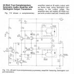
4x 2SC830. TO-66 case. quasi-complimentary configuration. 200W per channel. distortion characteristics unknown, but believed to be good due to the # of compliments received of the sound quality. the trafo is split secondary but the PSU is configured in an unusual way. the CT is ground, but there is a rectifier diode going from each hot leg of the secondary to the + rail, with the cathode pointed to the + rail and the anode toward its respective hot leg. there is no - rail. so rail voltage ends up sqrt(2) * 1/2 voltage between hot legs of secondary side of trafo.
hence why when those two rectifier diodes shorted the trafo was shorted across the reservoir cap. between one hot leg and CT on the top half of the cycle and the other hot leg and CT on the bottom half.
and no fuses designed into the unit. none whatsoever.
(for beginners reading this, a large value capacitor looks like a piece of wire to AC cuz Xc = 1/2*pi*f*C)
200 wpc from 4 2SC830's? Not a chance. What's the rail voltage, 60V maybe?
The old-school 2-diode center tapped bridge is the way they used to make B+ supplies with tube rectifiers. It had he advantage of reduced secondary current over a 4-diode full wave. You don't see that much anymore, except for low current supplies.
What I was referring to about 'split secondary' was the driver transformer. A lot of amps from that era used them, as opposed to a compelmentary driver transistor pair. You'd see it done with old PNP Ge stages all the time (those were usually TO-3's). The trafo had two secondaries, each one driving the Vbe junctions of the output pair out of phase. It had the advantage of separating the DC (bias) from the AC (signal).
wg_ski said:200 wpc from 4 2SC830's? Not a chance. What's the rail voltage, 60V maybe?
76V last time i measured it. and since P = V*V / R its easy to see P = 38 * 38 / 8 = 180W. actually a 7.22 ohm load would be required to drive it to a full 200W peak. so 100W rms per channel for 8 ohm, 200W rms per channel for 4 ohm. handles 4 ohm loads nicely. vibrates dishes in the neighbors house if i get too trigger happy with the vol control
wg_ski said:
The old-school 2-diode center tapped bridge is the way they used to make B+ supplies with tube rectifiers. It had he advantage of reduced secondary current over a 4-diode full wave. You don't see that much anymore, except for low current supplies.
thats good to know. yeah since i dont work on tube stuff this was only time i ever saw a PSU like that so i had to go over it a few times before i figured out how it worked.
wg_ski said:What I was referring to about 'split secondary' was the driver transformer. A lot of amps from that era used them, as opposed to a compelmentary driver transistor pair. You'd see it done with old PNP Ge stages all the time (those were usually TO-3's). The trafo had two secondaries, each one driving the Vbe junctions of the output pair out of phase. It had the advantage of separating the DC (bias) from the AC (signal).
does driver transformer mean the same thing as output coupling transformer? like those in RF amps? in that case, this amp didn't use an output trafo, just a pair of output coupling caps.
best regards
oh i see you mean a trafo between the VAS and OPS to set the bias in the OPS by feeding the bias voltage into the CT? to be able to use non-complimentary devices?
no this amp is not configured like that. its just standard solid state quasi topology with bandaxell diode improvement.
no this amp is not configured like that. its just standard solid state quasi topology with bandaxell diode improvement.
was just thinking ....
how was such a device as my 70s RCA allowed to be sold on the consumer market without any form of overcurrent protection system (such as fuse) that could have resulted in fire?
i mean, i believe the likeliest failure scenario was the left channel OPS blew, shorting the collectors to the emitters of the OPS transistors. this in turn caused a massive overcurrent condition in the PSU because at this point the top and bottom rails were essentially tied together due to the shorted OPS transistors. this overload caused the rectifier diodes in the PSU to overload and fail as well, shorting out the secondary winding of the main trafo. this, of course, could have easily led to a fire.
if this had happened while the wife was out shopping and left the radio on while she was gone, she could have returned to a burnt out house, all because someone was to lazy or stupid to install a ten cent fuse.
so what i am wondering is how was equipment like this allowed to be sold? isn't that what that "UL" approved sticker is for, to say this electrical appliance is safe?
now if anyone has a schematic for this thing (or a similar RCA product)
RCA schematic
Attachments
- Status
- This old topic is closed. If you want to reopen this topic, contact a moderator using the "Report Post" button.
- Home
- Amplifiers
- Solid State
- so just how good are you guys?