check this out .....
reading my own post come across this idea .....
one of the first boards i ve made for a P3 was made with anything available in the shop ....it was just for listening purpus so at this point no matched ltp transistors ....also nothing realy special for ltp just picked up a couple of bc 559 from the box .
at this point the pcb was made but no care has been taken for ltp transistors to be attached next to eachother for better thermal stability .
so constructed and used about 100 ma idle that actually produced some good ammount of heat in the heat sink .....
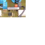
reading my own post thought about gluing a small piece of aluminioum creating something like a bridge above the transistors ( look at photo ) to create some thermal control between the ltp transistors since they were located almost 2 cm from each other ..... then ooooops temparture droped .......... any idea why ??????
reading my own post come across this idea .....
one of the first boards i ve made for a P3 was made with anything available in the shop ....it was just for listening purpus so at this point no matched ltp transistors ....also nothing realy special for ltp just picked up a couple of bc 559 from the box .
at this point the pcb was made but no care has been taken for ltp transistors to be attached next to eachother for better thermal stability .
so constructed and used about 100 ma idle that actually produced some good ammount of heat in the heat sink .....
reading my own post thought about gluing a small piece of aluminioum creating something like a bridge above the transistors ( look at photo ) to create some thermal control between the ltp transistors since they were located almost 2 cm from each other ..... then ooooops temparture droped .......... any idea why ??????
Attachments
MJL21193 said:What happened to the layout?
Did we scare you off IntArt?
i am waiting for some parts from mouser and partsexpress.
i will do the pcb this weekend or early next week.
Hi. This amplifier can be improved?
What their opinions?
I say curent-mirror, like this:
Whit Re1 = Re2 = 100ohms.
And add Re(Q1) = Re(Q2) = 22ohms? (constant gm degeneration)
Look Audio Power DesignHnadbook by Dougles Self pag84.
I would like to know your views
Q9(BD548) can be replaced with BD139 to mount a heatsink.
And finally sorry for my english
The basic current mirror on the input Long Tail Pair (LTP) is often rejected by designers due to an aledged reputation for not sounding as good as using resistors for the collector load.
It seems that this disadvantage can maybe overcome by adopting one of the more precise (and complicated) mirror as the collector load.
Emitter degeneration reduces gain and increases input linearity. Compromise again.
It seems that this disadvantage can maybe overcome by adopting one of the more precise (and complicated) mirror as the collector load.
Emitter degeneration reduces gain and increases input linearity. Compromise again.
By haven wood - Hi. This amplifier can be improved?
P3a is a simple amp ,but you can add more blocks (like mirror).
You get better balance between differential (Q1/2),
and 3-6 DB more gain. Replacing q9 with the BD is good,
but since this is a CPF output (read in selfs book) ,direct
couple with Q5 or 6 (separate heatsink,not main one)for thermal compensation.
You can go all the way and get a killer amp with a few more trannies (like in attachment) coming close to some IP
amps($300) with almost no distortion and better power
supply filtering (psrr).
OS
Attachments
By andrew T. - It seems that this disadvantage can maybe overcome by adopting one of the more precise (and complicated) mirror as the collector load.
Most definitely, between no CM and having one..better soundstage.. but with the more sophisticated current
mirrors Very detailed sound is possible...
the buffered widlar and wilson only add 1-2 components
for near perfect balance of Ic.
(see attachment)
OS
Attachments
Hi, news.
I mount the amplifier in a prototype board (not protoboar).
I measured: (Supply +18 -18V)
VR1 min => Class B
Vce(Q9) = 1.00 to 0.99V
V(R13) = 0.00V
Vout = 17.47Vcc
VR1 max => Class A
Vce(Q9) = 2.07V
V(R13) = 0.723V (Iq = 2.2A)
Set Iq = 100mA => Vout = 17.32Vcc and Q8(TIP33C) is hot.
I´m use Q7=TIP34C and Q8=TIP33C
VR1 = 5k and R16=2k2
What I'm doing wrong?
The offset is much.
follow up ......
the particular P3 board i constructed is now equiped with matched ltp pair ( under andrewT sugestion IE bridge matching ) but also have thermal junction .....
to my opinion this has made the amp more acurate and with more tight bass also the high sounds just a bit cleaner and finally had a vrey serious effect in the offset that actually droped to almost 25mv ( previously 75 )
yet again the all thing as is .....very clearly is effected from oustide temeperature and amplifier will increase its operating temperature depending on the room temperature .....
still very very happy with the particular amplifier
happy regards sakis
Re: follow up ......
I love your new look
Nico
sakis said:the particular P3 board i constructed is now equiped with matched ltp pair ( under andrewT sugestion IE bridge matching ) but also have thermal junction .....
happy regards sakis
I love your new look
Nico
Re: check this out .....
Originally posted by sakis reading my own post thought about gluing a small piece of aluminioum creating something like a bridge above the transistors ( look at photo ) to create some thermal control between the ltp transistors since they were located almost 2 cm from each other ..... then ooooops temparture droped .......... any idea why ??????[
can thermal matching (not only hfe matching) decrease the offset at the output?
regards..............
Re: Re: check this out .....
mjf said:Originally posted by sakis reading my own post thought about gluing a small piece of aluminioum creating something like a bridge above the transistors ( look at photo ) to create some thermal control between the ltp transistors since they were located almost 2 cm from each other ..... then ooooops temparture droped .......... any idea why ??????[
can thermal matching (not only hfe matching) decrease the offset at the output?
regards..............
It can HFe increases with temperature. If two devices have different thermal gradient dT/dt then they will perform differently, and worse if glued together.
The amp works ok, Q1 was broken.
I change a little the input stage. I´m use figure (b)
Now, can I change Q9(BC547) for BD139?
The circuit requires some modification?
For the pcb:
Q5 and Q6 are placed in the heatsink with the output transitor?
Or are placed together in a separate heatsink?
Iq = 100mA and Vcc = +/-20V
I change a little the input stage. I´m use figure (b)
An externally hosted image should be here but it was not working when we last tested it.
Now, can I change Q9(BC547) for BD139?
The circuit requires some modification?
For the pcb:
Q5 and Q6 are placed in the heatsink with the output transitor?
Or are placed together in a separate heatsink?
Iq = 100mA and Vcc = +/-20V
new look
the picture belongs to patsy kensit as she looks arround the 1992..... i think is the sweetest sexiest litle thing i ve ever seen in my life .....
as you may notice she is thin ...or even better skinny !!!! so i have a thingy with skinny girls ....which actually made a question of and drop it to my pshychotherapist ....
he said to me :
you like skinny girls cause you probably look at them as amplifiers they must be able to be "handy" easy to put your hands on , small but effective ....and so on and on and on ha ha ha !!!!!
Nico Ras said:
I love your new look
Nico
the picture belongs to patsy kensit as she looks arround the 1992..... i think is the sweetest sexiest litle thing i ve ever seen in my life .....
as you may notice she is thin ...or even better skinny !!!! so i have a thingy with skinny girls ....which actually made a question of and drop it to my pshychotherapist ....
he said to me :
you like skinny girls cause you probably look at them as amplifiers they must be able to be "handy" easy to put your hands on , small but effective ....and so on and on and on ha ha ha !!!!!
Attachments

Re: Re: Re: check this out .....
Different Dt/dt is not what shows when a matched pair are in the jig.
However, when testing jFETs, then they definitely have different slopes, and one has to find similar Idss and similar slopes, to then select matched pairs. The slope is effectively Gm.
why would two matched BJTs have different dT/dt? I thought this was pretty near fixed by the physics.Nico Ras said:
It can HFe increases with temperature. If two devices have different thermal gradient dT/dt then they will perform differently, and worse if glued together.
Different Dt/dt is not what shows when a matched pair are in the jig.
However, when testing jFETs, then they definitely have different slopes, and one has to find similar Idss and similar slopes, to then select matched pairs. The slope is effectively Gm.
- Status
- This old topic is closed. If you want to reopen this topic, contact a moderator using the "Report Post" button.
- Home
- Amplifiers
- Solid State
- P3A layout