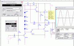
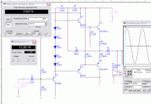
Simulated performance with modern devices below.
Close to the original, with some changes.. I tried a few different combinations, with different results with a few devices.
Using a diode string of 5 and increasing the bootstrap R's put the idle current and full power current close to his specs.
Anyone have other possibilities in mind? Different devices? I'm just probing around in the dark here, as I'm not as knowledgeable as I'd like to be.
Attachments
0.02 % THD
at 12 Watt RMS
is a very good output stage
Refering to my own (and Hugh 'AKSA' Dean) criteria = Max 0.05% THD
for my hi-fi amplifiers.
I have this target value, because there are no certain evidence
that human ear + mind perception
can hear distortion at 0.10 % THD levels.
Of course, your THD figure may be a little bit higher in real circuit.
This comes from the fact that you use Ideal 40.0 Volt Supply, in spice.
This and some copper rail issues in your PCB practical layout
will add some distortion, for sure.
How much, depends on your Power Supply, including transformer size + Caps filtering + wiring.
Also real loudspeaker is a more difficult load, than pure 8 Ohm resistance.
One guess would be, that you will endup around 0.05-0.10 % THD.
At 8 Watt RMS output into speakers.
As www.firstwatt.com tells us, a good sound quality at First, 1 Watt and below is most important.
And your output stage will perform very well, in real life,
at those output levels.
At least, this is my own thinking, speculation.
But we do not know if I am right.
Lineup
Hi Jez,
You can find a PDF copy of this document at IEEE Xplore - An adjustment-free complementary power amplifier
There's a link to the document (PDF) on the lower left where it says "Access this Document". You don't have to log in.
Regards Tony.
This URL isn't exist in the formerly kind; now it's an other
There are different "adjustment free" topologies. I know the follow:
1) Quad 405 (current dumping)
http://www.fralu.de/images/qaud405.jpg
Quad 405 Information Page
2) simplefield current dumping
http://www.mikrocontroller.net/attachment/63841/Audioverst_ker.png
http://www.elv-downloads.de/service/manuals/400W-Verstaerker/07903-400WattVerstaerker_km.pdf
3) servo controlled bias and offset (see attachement and older TAA edition - only N-Channel MOSFET amps)
The topologies from #22 and #23 are actually not "adjustment free" for the idle current through the output cause the depend of tolerances to the threshold voltages (diodes, Ube power buffer).
Attachments
Last edited:
Member
Joined 2009
Paid Member
Refering to my own (and Hugh 'AKSA' Dean) criteria = Max 0.05% THD
for my hi-fi amplifiers.
I have this target value, because there are no certain evidence
that human ear + mind perception
can hear distortion at 0.10 % THD levels.
Interesting how views change over the years
This URL isn't exist in the formerly kind; now it's an other
There are different "adjustment free" topologies.
I would to add one more to the list: Dr Bora's DOGC - http://bas.elitesecurity.org/dogcE.html
I am listening to the low-power version: DOGC-Mk3 and it sounds sweet. It is simple to build and the amp runs warm but not as hot as the regular class-A.
Member
Joined 2009
Paid Member
I found out the meaning for DOGC - "Death of GainClone". I googled it and found the following DIYA thread - http://www.diyaudio.com/forums/solid-state/69782-death-gain-clone-31.html
Dr. Bora changed the input devices to MOSFETs and modified widowsmaker's design to run the driver MOSFETs at Class-A. I have to say Dr. Bora version sounds good and the DC servo works well - the output DC offset voltage is very low.
Dr. Bora changed the input devices to MOSFETs and modified widowsmaker's design to run the driver MOSFETs at Class-A. I have to say Dr. Bora version sounds good and the DC servo works well - the output DC offset voltage is very low.
- Status
- This old topic is closed. If you want to reopen this topic, contact a moderator using the "Report Post" button.
- Home
- Amplifiers
- Solid State
- "An Adjustment-Free Complementary Power Amplifier" by J.Diamond

