Where to begin ? Well I wanted to see just what was and wasn't possible with HEXFET's. I have sometimes been a bit less than complimentary about them as audio devices, but thought it about time I gave them a whirl.
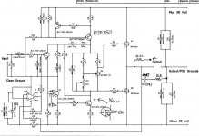
Some of you will be familiar with my MOSFET amp on this forum which uses Laterals FET's and that circuit formed the starting point for this little adventure.
Why stick with an existing design -- because it's tried/tested and above all else, it sounds great.
Right on to the HEXFET's -- prone to oscillation, prone to thermal runaway, not to mention the unreasonable high gate threshold voltage-- no they have no place in linear audio. 10 minutes then to show that they really are that bad. Er well not quite -- I was impressed ( actually very impressed ), and one thing led to another such as seeing if they could be taken out of the feedback loop altogether.
So here it is, very much work in progress, but with a few actual shots to show what really happens.
What I really want to know ? Anyone --- how does taking the outputs out of the loop affect sonics.
Attachments
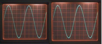
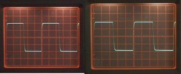
Now this is the killer. 20Khz into 2.2 mfd. The shot on the left is with the amp set up as before, the one on the right is with the 18K feedback resistor connected conventionally.
So the big question -- is this an approach worth pursuing ?
I had to readjust the 'scope sensitivity to fit it on, the amplitude didn't suddenly alter")
No output inductor either.
So the big question -- is this an approach worth pursuing ?
I had to readjust the 'scope sensitivity to fit it on, the amplitude didn't suddenly alter
No output inductor either.
Attachments
Yeah ,that's what i've been saying for years , hexfets are alright if you drive them hard
many years ago I used a irfp hexfet buffer with a 6n1p as a preamp built as a mu follower(also wth a hexfet). Thought that was pretty ok, might have been even better with just a little feedback..
Hmm I use lower gate resistance than the ones in the schematic hmm in fact i think I even tried with like 12ohms and 3ohm and so on, dont remember which one that was left there, I might even have replaced it with a wire hahaha hmm .. oh well
hola you all...
I bought a bunch of IRF640/IRF9640 to play with (they are cheap). I was looking to incorporate them into an output section ala Mr. Pass or one of Mr. Rollins(I do not have any small signal jfet's, but I have a bushel of small signal bjt's found in haflers)
Let us build somthing...
Regards, Elwood
I bought a bunch of IRF640/IRF9640 to play with (they are cheap). I was looking to incorporate them into an output section ala Mr. Pass or one of Mr. Rollins(I do not have any small signal jfet's, but I have a bushel of small signal bjt's found in haflers)
Let us build somthing...
Regards, Elwood
Mooly said:
Right on to the HEXFET's --
-------
-- I was impressed ( actually very impressed ),
-------
So here it is, very much work in progress
Mooly.
I actually posted a similar idea over 1 year ago.
Using HEXFET for Voltage 'VAS' amplification.
With some circuit schematics to illustrate...
Regards, Lineup
Solid State >Experimenting ... Volt Stage Hybridically
17th June 2007
http://www.diyaudio.com/forums/showthread.php?threadid=103678
lineup said:.
Experimenting with Voltage Amplification Stage.
There are many ideas about input & ouput transistors.
They are important too.
But to have a good and not to un-linear VAS stage .. is a real blessing.
At least when every other stages are trimmed to last decimal.
As you can see from attachment
this experimental setup use IRF TO-220 HEXFET for voltage amplification.
At a comparatively High Current.
My first version here, which shows good performance
uses JFET 2SK170 for input and TO-3 MJ15024 / MJ15025 for output.
.
Finally, this is according to my ideas.
How I have got the strength of diffrent transistor technologies:
1. JFETs are good for input. One quality is High Input impedance and low bias current.
2. MOSFETs are are good voltage amplifiers, they are fast!
3. BIG BIPOLAR working as Voltage Followers have low losses.
Even if now are very good Output FETs
that are just as good and probably will be the future ahead.
Audio Regards
lineup
Thanks for the comments,
Question first !! HOW DOES THIS APPROACH ACTUALLY SOUND- playing music- into real speakers and not having those outputs in the feedback loop.
That's the big question -- is it worthwhile now making a pair up properly for some serious evaluation -- yeah it's got to be -- otherwise I will forever wonder. In fact it would be easy to make the feedback takeoff point switchable for real comparisons.
In the all the above I never mentioned the quiescent current. Around 220 ma seemed the best compromise for driving low ohm loads. Go much below 180 ma and the transconductance of the output stage falls away, with the output across the load dropping, although no obvious distortion set in until around 150 ma or less. As Nikwal mentions they need driving hard. The 2N7000 Fet seems to work really well as a Vgs multiplier and was in thermal contact with one of the outputs--actually touching the package top, not the main heatsink. Stability of quiescent current is vital, not just to prevent runaway but also to ensure it dosn't fall too low after a loud passage due to over compensation. When the center leg of the outputs reaches "sizzle point" (technical term ) things are hot enough and the bias was very stable after reaching this point. The heatsink I use for testing is way to small, but useful !
) things are hot enough and the bias was very stable after reaching this point. The heatsink I use for testing is way to small, but useful !Hello Carlos,
It's even more impressive when you see how the outputs were wired. Thin (I mean thin) hookup wire from the PSU to the outputs. Same again from the two FET sources to the "output node" on the breadboard. Significant resistive losses here as they are not in the "loop". No decoupling at the outputs either.
Again this shows how stable the single ended input approach is in reality- particularly as regards layout.
Regards Karl
Gain 
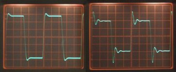
Have another look at post 4 picture 2. The one on the right with the ringing is the one with the feedback connected "conventionally". The one on the left is 20 Khz + 2.2 Mfd with the outputs not in the loop.
This is why I wonder how different this configuaration would sound. The feedback signal will not be influenced by the load, which is I suspect a cause of "coloration" with many amps.
Hello Lineup,
I feel like a Dinosaur sometimes you know. All this talk of simulators ( although I have been having a play with LT-Spice ) but to me you can't beat a box of real bits on the bench to really see what goes on. And it's quicker ! Well for me it is
Using a FET for the VAS. I used a 2N5551 here at first (Q5) which was fine, the test results were pretty much identical, but it was a bit near it's limits, current and power wise. And this is where the breadboard scores -- you can lineup or line up even, a row of different devices and try each in turn one after another, it's great you learn so much that way. That's how I came to try the FET. No other changes were required, it worked perfectly.
I love to try things like this -- even replacing Q1 with a Germanium -- just for fun, and you would be surprised !
The obvious thing to try next would be paralled outputs, but will that mean source resistors are needed for current sharing -- just think what that will do for the efficiency
More power -- more transistors
I feel like a Dinosaur sometimes you know. All this talk of simulators ( although I have been having a play with LT-Spice ) but to me you can't beat a box of real bits on the bench to really see what goes on. And it's quicker ! Well for me it is
Using a FET for the VAS. I used a 2N5551 here at first (Q5) which was fine, the test results were pretty much identical, but it was a bit near it's limits, current and power wise. And this is where the breadboard scores -- you can lineup
or line up even, a row of different devices and try each in turn one after another, it's great you learn so much that way. That's how I came to try the FET. No other changes were required, it worked perfectly. I love to try things like this -- even replacing Q1 with a Germanium -- just for fun, and you would be surprised !
The obvious thing to try next would be paralled outputs, but will that mean source resistors are needed for current sharing -- just think what that will do for the efficiency
More power -- more transistors
Mooly said:
Using a FET for the VAS. I used a 2N5551 here at first (Q5) which was fine, the test results were pretty much identical,
but it was a bit near it's limits, current and power wise.
this is also one of my points:
More Currents in the VAS.
To give good drive to output Gates/Bases.
And the higher input impedance of MOSFETs
makes the input stage more capable to drive such VAS into high current.
Anyway, we do not often see HEXFETs or MOSFETs used in VAS.
I know a couple of guys have done this.
And it works. And it is worth a try to see what can be achieved this way.
Evenso, of course, using the normal bipolar VAS works
.. often in combination with using pre-drivers in output stage.
I need Q3 and Q5 on heatsinks really if I am to up the VAS current, something I will probably try. It seems more elegant doing that than adding emmiter or source followers to the VAS, which in any case would not be compatible with taking the feedback away from the outputs.
There are so many posibilities
There are so many posibilities
Hi Karl
A real circuit, built and tested! Around here that makes it interesting solely for that fact. I've become a big fan of hexfet outputs. As for thermal bias, the zero temp co for hexfets is many amps, so they need to be compensated as BJT’s do when bias is only a couple hundred mA. But they are a little bit more forgiving than bipolars. Also since they are so fast, gate stopper resistors are a must.
It appears that you’re loosing about 2V at the peak of the wave form with the load, since the fets are not in the feedback loop. Vgs increases as the transconductance increases so you loose volts at the output, wrt the transfer characteristics, Vgs vs Id. What does the wave form look like driving a speaker instead of a resistor? Since gate drive is more related to transconductance than the input signal, the transconductance change is not exactly linear or in perfect phase, because a speaker is not a resistor.
Have you tried using EC yet? The idea is to use local feedback to apply extra voltage to the gate to cancel the effect at the output so that it would still be 16 Vp regardless of load, IOW less distortion. If you really want to get the best out of hexfets, you will find this paper by Bob Cordell interesting. Without EC, I think it is a bit much to ask the input stage and VAS to correct the high frequency nonlinear errors associated with these transistors. IMHO, without EC they aren’t really that great other than they can take a lot of abuse. In my hexfet amp, the EC and output stage is not in the fb loop, just a follower. Seems to work just dandy. I can amplify 400KHz with it
Here are some waveforms showing the output and error signals from a different mock up EC following stage I made, similar to Bob’s. The sine waves are 5V/div and the difference signals are 1V/div. All driving 5 Ohms resistive. Notice the phase shift as frequency increases. This circuit is obviously not quite perfect but it shows the extent of the correction circuit action.
30KHz
100KHz
200KHz
A real circuit, built and tested! Around here that makes it interesting solely for that fact.
I've become a big fan of hexfet outputs. As for thermal bias, the zero temp co for hexfets is many amps, so they need to be compensated as BJT’s do when bias is only a couple hundred mA. But they are a little bit more forgiving than bipolars. Also since they are so fast, gate stopper resistors are a must. It appears that you’re loosing about 2V at the peak of the wave form with the load, since the fets are not in the feedback loop. Vgs increases as the transconductance increases so you loose volts at the output, wrt the transfer characteristics, Vgs vs Id. What does the wave form look like driving a speaker instead of a resistor? Since gate drive is more related to transconductance than the input signal, the transconductance change is not exactly linear or in perfect phase, because a speaker is not a resistor.
Have you tried using EC yet? The idea is to use local feedback to apply extra voltage to the gate to cancel the effect at the output so that it would still be 16 Vp regardless of load, IOW less distortion. If you really want to get the best out of hexfets, you will find this paper by Bob Cordell interesting. Without EC, I think it is a bit much to ask the input stage and VAS to correct the high frequency nonlinear errors associated with these transistors. IMHO, without EC they aren’t really that great other than they can take a lot of abuse. In my hexfet amp, the EC and output stage is not in the fb loop, just a follower. Seems to work just dandy.
I can amplify 400KHz with it Here are some waveforms showing the output and error signals from a different mock up EC following stage I made, similar to Bob’s. The sine waves are 5V/div and the difference signals are 1V/div. All driving 5 Ohms resistive. Notice the phase shift as frequency increases. This circuit is obviously not quite perfect but it shows the extent of the correction circuit action.
30KHz
100KHz
200KHz
- Status
- This old topic is closed. If you want to reopen this topic, contact a moderator using the "Report Post" button.
- Home
- Amplifiers
- Solid State
- New Design-HEXFET Poweramp. Sonic benefits of this approach.