My recent posts have me very interested in trying to lower my amplifier's DC offset as much possible, but my amp didn't come with a trimpot for that purpose.
Based on the attached circuit, is adding a DC offset trimpot as simple as putting one in a particular spot between two transistors? Is it really that easy, or do you need to create a whole new circuit?
-Bryan
Based on the attached circuit, is adding a DC offset trimpot as simple as putting one in a particular spot between two transistors? Is it really that easy, or do you need to create a whole new circuit?
-Bryan
Attachments
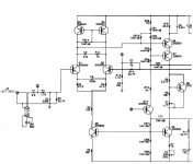
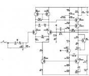
This is one way of doing it:
http://headwize.com/ubb/showpost.php?fnum=3&tid=5536&pid=42615&fpage=2
A pot instead of (or in parallel with) R3/R4 can also tune the DC-offset.
http://headwize.com/ubb/showpost.php?fnum=3&tid=5536&pid=42615&fpage=2
A pot instead of (or in parallel with) R3/R4 can also tune the DC-offset.
re:
In my manual the P2 pot is called a "Balance control"and its purpose is as "a distortion control that requires specialized test equipment to adjust".
Not knowing exactly what P2 does, I hate to change the factory setting as the pot is fixed with a dab of paint.
I like the idea of substituting a pot for R3/R4, I'll let you know what the outcome is...
-Bryan
1 or 2 pots?
I need some help deciding how to place the trimpots mentioned above........Which would make more sense?
- Replace both R3 and R4 with separate trimpots (I'm thinking 100ohm to give me some range).
- Or replace just one of the resistors with a trimpot, and dial it up/down to in to zero out the DC?
I would think it tricky to keep separate pots in 'synch'. Thanks in advance for advice.......Bryan
Just how much is your DC offset now?
Would it make any sense to match a new pair of diff transistors and see if that helped?
While changing R3 or R4 will lower the DC offset isn't that going to be counter productive because the pair would no longer be matched?
Would it be possible to add a DC servo to the circuit to lower the DC offset?
It's not bad now (13mv, 20mv) but when I bridge the channels it goes to 80mv. My other amp a Musical Concepts Xl280 w/PA3 with 1mv, so I'd like this amp above to be equally low.
I was just sorta hoping there was an easy method to add a DC offset adjustment to a Hafler 1200/9130 that doesn't have one.
In terms of re-matching the input transistors, I would love to do that. Too bad noone online offers a trustworthy service of matching transistors for audiophiles(!). Or do they?
I think your safest bet is to follow the instructions in the link above, not adding a pot instead of R3/R4. It was just an example of how it can be done. A trimpot/resistors from rails to negative input will do the same job (manually) as a DC servo. Though it's not cheaper than a servo circuit, it's more straightforward.
Your P2 is to set the bias current to the VAS transistors and should have nothing to do with offset.
Your P2 is to set the bias current to the VAS transistors and should have nothing to do with offset.
reiver said:
In terms of re-matching the input transistors, I would love to do that. Too bad noone online offers a trustworthy service of matching transistors for audiophiles(!). Or do they?
I have a cheap multimeter that measures the gain of transistors.
Maybe he meant us not being able to buy matched complementary transistors. If you buy a batch of 100 NPN's that turns out to have Hfe spread between 120 and 150, no multimeter will do any good if your 100 PNP's have a Hfe 60 - 80.nigelwright7557 said:
I have a cheap multimeter that measures the gain of transistors.
I would also be interested in buying reasonably matched batches of transistors.
reiver said:My recent posts have me very interested in trying to lower my amplifier's DC offset as much possible, but my amp didn't come with a trimpot for that purpose.
-Bryan
hi.
You can not cange the current up and down in VAS, too much,
without get the risk that VAS will not work properly.
Question:
What was was the original resistor, R, that you replaced with 10 Ohm + 500 pot?
The original needed current in VAS should be: ~0.7 Volt / R.
-------------
To match the offset I would:
1. Match the Q1 and Q2 as close as possible.
2. Increase R3 and R4, to maybe 100 Ohm.
As each of Q1 and Q2 runs at ~ 0.5 mA, this would give a drop of ~ 0.050 V ( 50 mV )
across R3, R4.
Which is not too much anyway. ( I have seen hifi amplifiers with 300 mV drop here )
=============================
Matching 2 NPN transistors is not that difficult.
If those 2 transistors is bought from same place at same time,
then if you match for Volt B-E,
you usually get 2 transistors with very close matched HFE gain, as well.
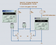
See my attachment, for the very simple, but working match circuit you can use.
Nelson Pass recommends similar easy test, for MOSFET and JFET matching, too.
-------------------------------------------------------------------------------
Instruktion.
Method 1.
You can measure each transistor and write down V b-e value.
Using Multimeter, like XMM2, in my picture.
Stick each transistor through the note paper, close to its value.
Method 2.
You can measure The Balance, between 2 Transistors.
Using XMM1, like in my picture.
When you have a difference of maybe like only 0-3 milliVolt
you have a good match in your amplifier.
Especially if you have increased R3 and R4 upto 100 Ohm.
-------------------------------------------------------------------------------
The value of 51.8 mV, as in my attached test, is of course a BAD MATCH.
Too big difference.
Lineup
Attachments
- Status
- This old topic is closed. If you want to reopen this topic, contact a moderator using the "Report Post" button.
- Home
- Amplifiers
- Solid State
- How to create a DC offset trimpot?