Ion,
Yes, you can PM me no problem at all.....
Clip will be around 5V off the rails, so if you use 15V, only 10V swing - 1.4W - will produce power.
If you raise the rail to 36V (25VAC trafo) then you will be able to extract a 31Vpp signal, which is around 14W, much better. But you will need to increase the quiescent current to 2A, and at around 16V across each mosfet, this will be at 32W device dissipation, which represents about the reliable maximum of the IRF150/9140 devices, and you'd better have 0.5 degreeC/W heatsinks ON EACH DEVICE.
Cheers,
Hugh
Anyone seen schematics of the McCormack amps? Are they public domain? I understand he uses bipolar outputs and mosfet drivers, is this true?
The DNA0.5 and DNA1 power amps used a MOSFET source follower driving a bank of paralleled BJT emitter followers. Think of a discrete IGBT and you would be on the right track.
AKSA said:Ion,
Yes, you can PM me no problem at all.....
Clip will be around 5V off the rails, so if you use 15V, only 10V swing - 1.4W - will produce power.
If you raise the rail to 36V (25VAC trafo) then you will be able to extract a 31Vpp signal, which is around 14W, much better. But you will need to increase the quiescent current to 2A, and at around 16V across each mosfet, this will be at 32W device dissipation, which represents about the reliable maximum of the IRF150/9140 devices, and you'd better have 0.5 degreeC/W heatsinks ON EACH DEVICE.
Cheers,
Hugh
I'm running it from +18 / -14 rails with fan-cooled heatsinks and a dc servo to get rid of the 0.7V offset.
I have been thinking on the circuit and i'm pretty surprised that you found a -3dB cutoff point at 80KHz, my impression is that the dominant pole is created by Cgs-R0-Rg at arround 6KHz, but having a 80 dB open-loop gain this should be able to go a couple of decades further to 600KHz (at 200KHz the capacitances of the ccs and driver may create extra poles and give a slope of 60 dB's /decade).
(Everything estimated assuming the driver has an early voltage of 70V and 40 mS/mA transconductance.)
What i would like to do is to degenerate a bit the current source or the driver to place the pole at 25-60 Khz for the sake of having constant feedback over the whole audio band, which seems to be very, very, very desirable.
PM does not work with you so hope there is no problem to ask there, i asked this to add it to a class A amp i was developing and posting in another thread, but you came up with part values so fast that i have to think that you might have already developed this for yourself before and you may not want me to post the schematic and spoil your work. Anyways there is something "tubby" about the sound of bjt EF in class A (specially done by the TIP142) that i belive to be the spirit of my amp so i won't post anything soon.
Marc
EDIT: Clipping actually happens at 7V from the rails (there is a 1.5V voltage drop at the gate stopper and the mosfet needs a couple of volts over the source voltage to give 3A. The good point is that clipping looks fine.
Hi Marc,
I've just checked my user settings, all is well, PM is enabled, so PM me if you wish.
Your comments about 3dB points look correct, yet I measure 3dB down at 75KHz full power into 8R. Not sure what is happening there, but I think this demonstrates you should have faith in your hunches and not put too much emphasis on the calculations until you have built and measured it.
I use a unipolar 50V supply at 2.8A with 2 x 9140 and 2 x 150 mosfets, and pull 28W into 8R at 46Vpp.
5mA drive to the MPSA42 driver is used.
Hugh
Thanks VV,
Nordic,
The heatsinks are MF30-150s, rated to 0.35degree/watt (corrected). With 72.5W into each heatsink, the temperature rises around 25C above ambient. On a day of 25C, this is 50C, quite hot, and on a day of 38C, common in these parts, sink temperature is 63C, which is on the verge of unbearable beyond about ten seconds.
Four such heatsinks, and for two channels in monoblock config, gives a total heat output around 290 watts for 2 x 28W rms into 8R.
In about ten years operation over four pairs of these monoblocks, I have never seen a mosfet failure, which is a real credit to the thermal robustness of these devices.
Hugh
I have just realized that the Cgd is multiplied by the gain of the output stage in this circuit. Assuming the degenerated transconductance of the mosfet to be arround 1.25 S at these currents and the loudspeaker impedance to be arround 8Ohms this gives a voltage gain of 10, so Cgd will be seen as 5 nF and Cgs is arround 1.5 nF, so total capacitance is arround 6.5 nF.
This does not explain the cutoff at 80 KHz but it should limit the slew rate at arround 10V/usec. Hugh, are you sure about your measurements?
This does not explain the cutoff at 80 KHz but it should limit the slew rate at arround 10V/usec. Hugh, are you sure about your measurements?
Ion,
I'm sure about the FR, no question, not so sure about slew rate.
Not sure where you get a voltage gain of 10 from. The OLG must be in the 80dB range, while CLG is unity. My circuit is a buffer, Av = 0.995. You need to fix the bias on the base of the driver at around 2V below Vcc/2 for max efficiency at clip.
I'm using 0.47R degeneration on each mosfet source and 2.8A total current.
Driving current is 4.2mA for BOTH gates.
HOWEVER, have you built, tested, auditioned and noted the sonic qualities of this circuit? I cannot indulge a long, detailed technical discussion of this circuit because it measures well, is innovative and works to my complete satisfaction. I do not have the time or the math to enjoin a long chat about the technical aspects, I am sorry.
In truth, while I sympathise with the desire to know every last detail, I'm more interested in operational parameters, such as Zout, which measures 38 milliohms, and frequency response and THD, which are outstanding.
Hope this helps,
Hugh
Hi,
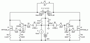
I did a quick sim of a slightly different stage: balanced and choke-loaded output instead of single-ended + CCS, resistive load on the driver BJT, inversed polarities (2xIRFP244's + 2N3906 NPN per side), 3A bias, 20V supply. The values I get from this setup are in the same ballpark than what is reported by Hugh and ionomolo:
150kHz power bandwidth for 30W @ 8Ohms
20V/µs slewrate (diff.)
Zout <= 10mR up to 20kHz, flat out to 10kHz, thus THD (< 0.015%) & feedback also. With CCS-loaded driver this gets even better...
Of couse this is just the "virtual world", still I was really astonished about the perfomance level of such a simple circuit. A very interesting Class-A design idea this BJT+MOSFET CFP is, that's for sure, wether CCS-loaded or not...
- Klaus
Attachments
KSTR said:I did a quick sim of a slightly different stage: balanced and choke-loaded output instead of single-ended
-----
..... I was really astonished about the perfomance level of such a simple circuit.
A very interesting Class-A design idea this BJT+MOSFET CFP is, that's for sure, wether CCS-loaded or not...
- Klaus
Great testing, Klaus.
I, of course, downloaded your interesting attachment circuit.
This deserves some MultiSim exploration, by myself, too.
Thanks, KSTR, for posting 'your' circuit

Lineup
-----------------------
PS.
Hugh 'AKSA' Dean doesnt post often in Blowtorch. With the other of our wellknown Audio Elite Troupe/Group.
Probably just because he does not fancy. It is not because he can not contribute, at that level.
But AKSA most often gives us his very good points in more normal topics.
DX Destroyer has discovered the thinkings of Hugh Dean.
And so have I.
Which gives some credits to my Lineup knowledge, as well.
Because .....
It takes one - to know one
... how can anybody say: 'This is a good car' / 'This is not a good car'
If not know what a good car / bad car is like.
In order to appreciate the information of a person.
Judge it as Valuable.
You need to have The Knowledge and Experience to make a good judgement.
Or you will miss most of the valueable things contributed.
DS.
Lineup,
Give the credits to Steve Eddy who proposed that center-tapped choke loading in the BT-thread the other day (and he would probably need to credit some genius in the early tube era). This choke would be an expensive and big piece of copper & iron (big toroid), to get the required high L, low DCR and saturation headroom. But it's not directly in the signal path, which is nice.
There is quite a bit potential for tweaking (I already tried a few things, including cascoding the output to lessen Cdg impact (the PIM issue), next is a dynamic bias scheme, something along the ideas behind the LT1166 or some work of Edmond Stuart), but one of the key points is the voltage drive (Hugh mentioned that, I think), which would need to be of low impedance but current limited to protect the bases, etc etc... it is clear to see that to get a truly workable circuit there is some considerable effort ahead, no wonder Hugh spent quite a while on getting his amp to perfection, tube drive and all...
- Klaus
I have been playing with cascoding (The problem I mentioned is that a small voltage variation at the gate translates into a big voltage variation at the drain, so the Cgs needs to be charged and this limits bandwidth and slew rate).
Cascoding both the mosfet and the load i get 0.0015% THD (of course at maximum output and 20KHz, exactly 10 times lower than i get without cascoding), flatter output impedance and 0.3% THD at 1MHz full-power. I don't belive this can be done in practice but it gives a clue on what to expect.
The two transistors and the two voltage sources add extra complication, but 0.0015% THD worst case is very impressive, and $5 to get distortion cut down by 10 without objectionable things like extra feedback is a great deal (well, cascoding actually helps keeping feedback constant over the audio band, but keeping things constant is not objectionable).
I still get weird effects like "bumps" and ringing that depend on parameters like the idle current in both "main" ccs and bias ccs, but i havn't fully understood what is exactly behind these and i won't build a cascoded prototype until i get it.
This is in fact a complete amplifier with 100% nfb, but it concentrates the input stage and the vas on a single transistor. That avoids many distortion mechanisms as feedback is less delayed and there are less parts involved.
Dough, I have tried the "plain" version and it sounds great, with impressive transients and great detail. I still have to put it side by side with the bjt "soft'n'warm" class A amp to see what i prefer. Anyways i was a bit worried about the amp showing a behaviour that i did not understand and this may lead to an improoved version.
I have played with all circuit parameters on wonderland (spice) and probably the current bottleneck is the BC550. It is a great transistor (look at the datasheet for the beta vs ic plot) and it has a 200 MHz Ft at 10 mA's.
i still have to find something to drive it. At the moment i'm using an LM4562 which is nice but a bit "opampy". I will look for something like a single transistor x10 gain stage and hope it preserves the "purity" of the amp (maybe i will add a switch to use a tube, but not as single option because i belive that the sound from this stage is contradictory with the tubes).
Attachments
Klaus,
I designed a circuit just like yours with CCS loading about six years ago, even had the very heavy chokes wound professionally. But I have not yet built it, but it shares many characteristics with NP's circuits, looks a lot like an Aleph.
I have built about ten of the SE version in monoblock, using a tube driver. It is a sensational amplifier, with astonishing performance. I built my first back in 1994. There is nothing new under the sun......
Ion,
Drive the output stage with a tube. As NP has said, if you want it to sound like a tube, use a tube. I would suggest using 6DJ8 as it will run at lower voltages, easier to accommodate. Cap coupling is fine, since the feedback is forward of the cap. To reduce gain and improve the tube stage zout, you could use an anode-follower, see John Broskie's circuit.
BTW, I find it's better to learn about circuits by building and appraising them rather than using simulation. It's the phenomenon you wish to study, not the math simulation. Both are useful; but the phenomenon comes first and simple math is all that is required to set up a working circuit.
Lineup,
I do not contribute in Blowtorch for many reasons, but principally because I find the personalities there the rudest and most arrogant on this forum. In those circles, I really have nothing to contribute as they talk in mathematical abstracts, which I cannot see is relevant to good sound at all. If you closely look you find that they throw verbal barbs around without listening much to each other, rather like academics bickering.
Cheers,
Hugh
KSTR said:Lineup,
Give the credits to Steve Eddy who proposed that center-tapped choke loading in the BT-thread the other day (and he would probably need to credit some genius in the early tube era). This choke would be an expensive and big piece of copper & iron (big toroid), to get the required high L, low DCR and saturation headroom. But it's not directly in the signal path, which is nice.
There is quite a bit potential for tweaking (I already tried a few things, including cascoding the output to lessen Cdg impact (the PIM issue), next is a dynamic bias scheme, something along the ideas behind the LT1166 or some work of Edmond Stuart), but one of the key points is the voltage drive (Hugh mentioned that, I think), which would need to be of low impedance but current limited to protect the bases, etc etc... it is clear to see that to get a truly workable circuit there is some considerable effort ahead, no wonder Hugh spent quite a while on getting his amp to perfection, tube drive and all...
- Klaus
Which transistors do you use for cascoding? I have just found that the amp shows ringing on the botton half of sine waves when cascoded if either the current is low (< 2.5 A) or the gate resistor is big (> 150R). Are you getting similar results?
Do you have any explanation for that?
Attachments
AKSA said:Ion,
Use a tiny resistor between emitter and collector of the cascodes and set it up to drop around 200mV.
I have found this prevents lower waveform ringing,
Cheers,
Hugh
It seems that everything is fine now. It will take me a couple of weeks to do decent builds of these but i can't wait to hear them.
Thanks for all the help!
Hi there,
I've been playing with that MOSFET+BJT Siklai a bit more... and seem to have found a great circuit:
- 35W class-A @ 5.6R, at 140W total power dissipation, a good ratio
- no chokes, no caps, dc-coupled (balanced input)
- can handle occasional class-B transients at increased distortion
- pretty good distortion characteristics (<0.01% THD wc-conditions)
- completely flat Zout vs. frequency
- easy biasing and thermal compensation
- simple circuit, only the driver is cascoded but with resistive load
Details will follow, now I'll watch the soccer game...
- Klaus
- Status
- This old topic is closed. If you want to reopen this topic, contact a moderator using the "Report Post" button.
- Home
- Amplifiers
- Solid State
- ccs-loaded sziklai