Hello!
I have acquired an A3i, but when I pass audio through it there is severe distortion and an inconsistent volume coming from the right channel. There is no issues when the balance is set fully to the left, in fact the left channel seems to be completely fine. I have verified that its not faulty speakers. Has anyone come across this problem, and does anyone have any suggestions for fixing this?
Many thanks
Welcome to diyAudio ")
Without knowing your experience on working on these kind of things... well first easy things to check and confirm are that there is near zero volts DC across the speaker terminals. If that is OK switch the amp OFF and check the value of these two resistors. A low cost meter will show them as almost short circuit and that is fine. If they are high in value or open then we have a fault causing that.
If all that check OK then you could cross couple the inputs to the power amps and feed L to R and vice versa to see if the problem is in the power amp or preamp. Those are pins 3 and 5 on that left hand connector on the diagram. If you try that be very careful not to short the two 34 volt rails to anything.
Also, is the fault consistent on all inputs? That is really the fist thing to check.
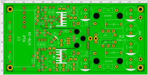
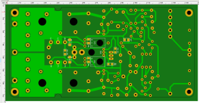
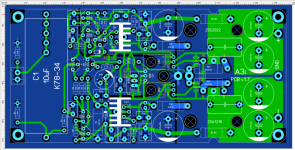
*.Lay and Gerber - as you wish...It would be nice to make a replacement PA board for the A3i, from FR4 material, implementing all the mods, providing for a good thermal performance on the PCB.
Attachments

Dual 606 question now here:
https://www.diyaudio.com/community/threads/dual-606-transformer.408720/#post-7588501
Hi all, thanks for this thread. I am trying to restore my A3i which had distorded sound on one channel.
I replaced Q10, sound was fine again. I replaced Q8, sound was fine.
Then I proceeded to the LEDs. I replaced all four and now, the amp turns on with all LED lit up, but it makes loud humming (almost vibrating), and the relay never clicks on. LED type is OSG55133A-VV, maybe not the best choice because they are super bright. Any ideas what to check?
The LED's are used as voltage references to derive the constant current for the voltage amplifier stages and as such are extremely critical. You have almost certainly totally altered the design values by swapping these. If the current is higher than intended then the bias current of the output stage will be higher to. Also the dissipation in Q8 and Q10 will be higher, maybe damagingly so.
If you know the original currents (which depends 100% on the forward volt drop of the LED's) then you can recalculate the required new values for R12 and R17.
If you know the original currents (which depends 100% on the forward volt drop of the LED's) then you can recalculate the required new values for R12 and R17.
I see, thanks Mooly. I changed back to the old LED and the relay now activates again. However, the left channel distortion is back. It seems intermittent, at first it seemed related to the mute switch which I bypassed, but the distortion came back
I would like to replace the LEDs at some point, some of them have quite corroded legs. Do you have a suggestion for a suitable model? Or how I can recalculate resistor values given the ones I have.
I would like to replace the LEDs at some point, some of them have quite corroded legs. Do you have a suggestion for a suitable model? Or how I can recalculate resistor values given the ones I have.
Last edited:
Bad choice - these have built-in resistors and are not suitable for the role LEDs play in the A3i. What you need there is four standard, cheap, garden variety yellow-green (GaP, 565nm wavelength) LEDs with forward voltage drop about 2 volts.OSG55133A-VV
I would like to replace the LEDs at some point, some of them have quite corroded legs. Do you have a suggestion for a suitable model? Or how I can recalculate resistor values given the ones I have.
You should measure and record the voltages across the original LED's and also across R12 and R17. The voltage across the resistors allows us to accurately calculate the current, the voltage across the LED's is useful to know for reference. You need to stick to the same colour LED as well because forward voltage varies massively with colour.
I have worked some more on my amp, found a couple of cold solder joints on the Sankens which I fixed.
Also replaced Q11, Q12, D210, D211 as recommended.
Right now it works on both channels and sounds great, but Q8 and Q10 gets VERY hot. Is this a concern?
R12: 1.47V
R17: 1.47V
(both of these look a bit burnt)
LED101: 2.01V
LED102: 2.02V
LED1: 2.01V
LED2: 2.0V
I have on order some LEDs with forward voltage 2.2-2.4V, I have to change the resistors then?
Also replaced Q11, Q12, D210, D211 as recommended.
Right now it works on both channels and sounds great, but Q8 and Q10 gets VERY hot.
Is this a concern?Thanks. I get:You should measure and record the voltages across the original LED's and also across R12 and R17. The voltage across the resistors allows us to accurately calculate the current, the voltage across the LED's is useful to know for reference. You need to stick to the same colour LED as well because forward voltage varies massively with colour.
R12: 1.47V
R17: 1.47V
(both of these look a bit burnt)
LED101: 2.01V
LED102: 2.02V
LED1: 2.01V
LED2: 2.0V
I have on order some LEDs with forward voltage 2.2-2.4V, I have to change the resistors then?
This looks interesting, has it been tested?*.Lay and Gerber - as you wish...
- Home
- Amplifiers
- Solid State
- Cambridge Audio A3i repairs and mods