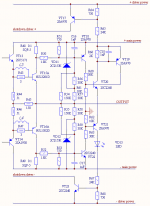
If current throw output transistor (VT15/16) is high, voltage on sense resistor 0.1 Ohm opens transistor VT18 or VT22. Circuit with resistors 50-59 and zenners varies open current as to limit power dissipation on output transistors. VT19-21 - trigger. It opens VT17 and VT23. Its must switch off driver’s cascade.
Kostya-M, thank you for your answer.
I cannot understand how it works. I am confused about how it will sense the overload and how i will set it for specific transistors.
I guess that this is a sample, as you wrote, do you have a schematic more specific?
I think that this could be help me more.
Thank you.
I cannot understand how it works. I am confused about how it will sense the overload and how i will set it for specific transistors.
I guess that this is a sample, as you wrote, do you have a schematic more specific?
I think that this could be help me more.
Thank you.
Hi Billys
Look at schematic by parts and only on upper half. Lower half works the same. Current throw VT15 makes voltage on R48. This voltage open VT18 throw R50. Sensitivity of this schematic is about 7 amperes and, in general, is defined by value of R48. But power dissipation on VT15 depend on current and voltage on transistor. Resistors R54, 56, 57 and zenner VD11 (15Volts) makes two linear approximation of hyperbolic curve of maximum power dissipation. When power dissipation on VT15 grows 150W, VT18 is opened and trigger on VT19-21 fixes this overload. Capacitor C16 removes short overloads. Often, value of C16 can be more greater, because power transistors allows short overloads.
This picture is part of schematic of my power amplifier that has maximum power 120 W on 4 Ohm load. Power voltage value is +-38V, driver voltage +-45V.
Andrew
This thyristor (trigger) don’t resets on zero voltage. Its need to switch off amplifier to reset. I think about autoreset schematic, but can’t solved it for my amplifier schematic.
Excuse me, I know English so so.
AndrewT said:Hi Kos,
does the thyristor reset on every half cycle of the output signal (i.e. on zero crossing)?
No, you need to power down. This is very similar with what I did almost 6 months ago in YAP http://www.diyaudio.com/forums/showthread.php?s=&threadid=128809&highlight= (schematic here: http://www.synaesthesia.ca/files/ops.gif ) but without the SOA circuit (using MOSFETs, that's not required).
Any part of my protection circuit is well known. I only compile it from standard elements. Thyristor as the element I don’t use in schematic. But trigger on VT19 and VT20 is thyristor is made from transistors. My schematic doesn’t shut output of amplifier, but only switch off driver. If output DC voltage will be greater than limit, then controller of amplifier switches off power.
Hi Kostya-M, thank you again for your answer.
If i have to add your protection system on this amplifier http://www.siliconchip.com.au/cms/A_100618/article.html what do i need to calculate and change?
The specs of the transistors are here http://www.datasheetcatalog.org/datasheet/on_semiconductor/MJL21193-D.PDF
If i have to add your protection system on this amplifier http://www.siliconchip.com.au/cms/A_100618/article.html what do i need to calculate and change?
The specs of the transistors are here http://www.datasheetcatalog.org/datasheet/on_semiconductor/MJL21193-D.PDF
Hello, Billys!
Where is no schematic sheet on the web page, only pcb sheet. Therefore I can’t analyze how driver works in this amplifier. Because of supply voltage is +-70 V (not of 40V as in my schematic), and emitters resistors 0.47 Ohm are greater than 0.1 in my, resistors nominal in safety scheme will differ from my. Supply voltage of this amplifier is large. It’s possible that needs to use three linear approximation – resistors R57 and 58 separate every on two and in points of junction add second zenner of higher voltage then VD11 and 12. Anyway, it’s necessary to recalculate resistors with proper attention.
Where is no schematic sheet on the web page, only pcb sheet. Therefore I can’t analyze how driver works in this amplifier. Because of supply voltage is +-70 V (not of 40V as in my schematic), and emitters resistors 0.47 Ohm are greater than 0.1 in my, resistors nominal in safety scheme will differ from my. Supply voltage of this amplifier is large. It’s possible that needs to use three linear approximation – resistors R57 and 58 separate every on two and in points of junction add second zenner of higher voltage then VD11 and 12. Anyway, it’s necessary to recalculate resistors with proper attention.
- Status
- This old topic is closed. If you want to reopen this topic, contact a moderator using the "Report Post" button.
- Home
- Amplifiers
- Solid State
- Overload and Short Circuit Protection