Another ambitious project! The goal: to build a sub amp that is capable of driving (up to) 1000 watts into a 2 ohm load.
Normal use for this amp would be a 4 ohm load, but for future consideration, I thought it would be better to over-build rather than just meet my immediate needs.
I am currently using a ~500 watt @4 ohm based on Rod Elliot's P68. This was my first ever amp build, and though it works very well, it looks pretty rough. I did it on an old circuit board recycled from a scrapped receiver. I sanded off all of the copper and wired all of the components point to point. Truly amazing it works at all! In another thread here, there's a picture of it (in the top right hand corner) and the sub it drives.
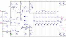
I have been planning this for a while now, and I've come up with a schematic that sims well and is relatively simple. Supply voltage is +/-70 volts from a 50-0-50, 850VA toroid.
During my last amp project (Patchwork ) I learned a lot, but I'm still nowheres near confident enough to try to pull this one off without some help and guidance.
Anyhow, here's the schematic. I ask for any advise and critical comment (good or bad).
Normal use for this amp would be a 4 ohm load, but for future consideration, I thought it would be better to over-build rather than just meet my immediate needs.
I am currently using a ~500 watt @4 ohm based on Rod Elliot's P68. This was my first ever amp build, and though it works very well, it looks pretty rough. I did it on an old circuit board recycled from a scrapped receiver. I sanded off all of the copper and wired all of the components point to point. Truly amazing it works at all! In another thread here, there's a picture of it (in the top right hand corner) and the sub it drives.
I have been planning this for a while now, and I've come up with a schematic that sims well and is relatively simple. Supply voltage is +/-70 volts from a 50-0-50, 850VA toroid.
During my last amp project (Patchwork ) I learned a lot, but I'm still nowheres near confident enough to try to pull this one off without some help and guidance.
Anyhow, here's the schematic. I ask for any advise and critical comment (good or bad).
Attachments
MJL21193 said:Another ambitious project! The goal: to build a sub amp that is capable of driving (up to) 1000 watts into a 2 ohm load.
Hi John,
quick look, should be fine - I don't see any obvious problems. I trust that the majority of electrolytics is off-board and you won't use the 330uF cap on its own.

Since you will use it for a sub-woofer why not band-limit it to say 2kHz, just in case there are some sputious in the input and you fry the voice coils.
Kind regards
Nico
a.k.a. Emitter follower, and mount the transistor on the main heatsink.Leolabs said:You may try to replace those bias diodes with 'diode connected transistors'.
") He has it in his other project - the patchwork. On the other hand the main goal here is a subwoofer amplifier, wich means bias is not a big problem here with the amp working in almost ~class B, so the diodes will work fine. It might be a problem, and the emitter follower can be used...if the amp was another class above like "Hi-Fi" or so, for improving the performance in higher frequencies....i think.
He has it in his other project - the patchwork. On the other hand the main goal here is a subwoofer amplifier, wich means bias is not a big problem here with the amp working in almost ~class B, so the diodes will work fine. It might be a problem, and the emitter follower can be used...if the amp was another class above like "Hi-Fi" or so, for improving the performance in higher frequencies....i think.Re: Re: 1000 Watt Sub Amp: Design / Build
Hi Nico,
Good to hear from you here. For the power supply, I'm not quite sure how much capacitance I need. The transformer is being used now in the "rustic" version with 10,000uF on each rail. It doesn't seem to run out of gas, even on the big power demands from movie soundtrack LFE through the Linkwitz Transform. For a lower impedance, I expect I should have more per rail - maybe 20,000-40,000?
Yes, thermal tracking with the diode string in contact with the heatsink. I will do the board layout to make this possible.
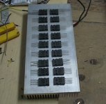
I did a fair bit of research on heatsink requirements for this amp. Using this formula: Pd = (Vpp^2 )/(R(Load)*2 * PI^2 to determine total dissipation at full power I get 490 watts at 2 ohm load. Lotsa heat! The heatsink I have for this has a thermal resistance of .37*/watt (BarrredBose on Ebay - 12" long, shown below). For continuous duty into low impedance I'd need some fans to lower the thermal resistance.
The fact that this amp will not be used for full audio spectrum, but limited to 80 Hz and lower, give a bit of breathing room. (hopefully)
Anyone with a better grip on the cooling requirements for this, feel free to chime in, especially if you think the heatsink is not enough. The one in the "rustic" version is a homemade job, with less mass than the new one. It doesn't get hot at all.
Here's the heatsink, with the 18 output devices laid out to see how they fit.
Nico Ras said:
Hi John,
quick look, should be fine - I don't see any obvious problems. I trust that the majority of electrolytics is off-board
Hi Nico,
Good to hear from you here. For the power supply, I'm not quite sure how much capacitance I need. The transformer is being used now in the "rustic" version with 10,000uF on each rail. It doesn't seem to run out of gas, even on the big power demands from movie soundtrack LFE through the Linkwitz Transform. For a lower impedance, I expect I should have more per rail - maybe 20,000-40,000?
Nico Ras said:Sorry John a quick question, how will you compensate for temperature, are the diodes mounted on the heatsink?
Yes, thermal tracking with the diode string in contact with the heatsink. I will do the board layout to make this possible.
I did a fair bit of research on heatsink requirements for this amp. Using this formula: Pd = (Vpp^2 )/(R(Load)*2 * PI^2 to determine total dissipation at full power I get 490 watts at 2 ohm load. Lotsa heat! The heatsink I have for this has a thermal resistance of .37*/watt (BarrredBose on Ebay - 12" long, shown below). For continuous duty into low impedance I'd need some fans to lower the thermal resistance.
The fact that this amp will not be used for full audio spectrum, but limited to 80 Hz and lower, give a bit of breathing room. (hopefully)
Anyone with a better grip on the cooling requirements for this, feel free to chime in, especially if you think the heatsink is not enough. The one in the "rustic" version is a homemade job, with less mass than the new one. It doesn't get hot at all.
Here's the heatsink, with the 18 output devices laid out to see how they fit.
Attachments
Since you are driving such a low impedance load, you may want to try raising your VAS current.
Your schematic shows 2x 3.3K resistors on 70 volt rail. I built a 350W 4 ohm amp, that uses 2x 2.2K 2W resistors to get 16ma for VAS. They get hot, and the VAS is warm on small heatsink, but I get good sound and drive, even at tested 2 ohm loads, even though the amp is rated four 4 ohm.
Since you want an amp RATED at 2 ohm...............
You may want to try 2x 1.5K ohms for VAS since 2 ohm load requires twice the regular current of 4 ohm. Just get some big 2W (or 5W) resistors so they can handle the power. Use a good VAS transistor and don't let it run too hot.
Also, since it's 1000W, if you have enough transistors, try 10 pairs of outputs. I used 5 pairs of MJL4281/4302 for 350W, and the output stage survived a shorted speaker coil and just blew the fuse.
Overkill is good, especially if you blow a speaker, or have any other fault, hopefully the fuse blows before the transistors because there's so many to handle the load.
Leolabs said:You may try to replace those bias diodes with 'diode connected transistors'.
Hi Leolabs,
I wanted to keep it as simple as possible, given the intended use for this I used the diodes. I boroughed heavily from Rod Elliot's P68 here, which is a class B. I added the third diode to give some quiescent current (~85mA/device as things are now). I may change my mind on this though...
kalmara said:
a.k.a. Emitter follower, and mount the transistor on the main heatsink.
My thoughts exactly, concerning the "hifi" quality. The diodes do the trick, but there are some drawbacks: the inability to easily change idle current and putting a limit on the VAS current. The VAS may be the biggest problem.
EWorkshop1708 said:Since you are driving such a low impedance load, you may want to try raising your VAS current.
Also, since it's 1000W, if you have enough transistors, try 10 pairs of outputs. I used 5 pairs of MJL4281/4302 for 350W, and the output stage survived a shorted speaker coil and just blew the fuse.
Overkill is good, especially if you blow a speaker, or have any other fault, hopefully the fuse blows before the transistors because there's so many to handle the load.
Hi EWorkshop1708,
The problem with raising the VAS current in the present configuration, is that idle current will also increase. The VAS is running with ~12mA right now. I'd like to increase it - up to 20mA or more (the device can handle it), but that means either removing one diode and let the amp run B or ditch the diodes and use a Vbe multiplier.
I'm wondering if it's really necessary to raise VAS current though. The simulation runs fine and the nature of the output stage, with the CFP providing tons of current for the outputs.
Am I seeing it right?
I worried about how many outputs to use. The one I use now has 4 outputs plus the CFP. It seems fine for 4 ohm loads. I searched on google and found
this site where the guy has a spreadsheet to figure out how many outputs are needed to maintain a safety margin. I found the 8/side was good with these devices at the 2 ohm load, given the intended use for the amp.
Also, the available space on the heatsink is limited. I could probably squeeze one more per side.
MJL21193 said:
Hi Leolabs,
I wanted to keep it as simple as possible, given the intended use for this I used the diodes. I boroughed heavily from Rod Elliot's P68 here, which is a class B. I added the third diode to give some quiescent current (~85mA/device as things are now). I may change my mind on this though..
Using diode connected transistors instead (collector tied to the base) is a good idea. You can use a low power, small die (for quick thermal response) TO-126 packaged device such as a BD139. They are much easier to mount on the heatsink than a string of 1N400X's. You can even screw them down onto the top of three of the MJL21193/4 trannies with the same three mounting screws. This makes the PCB layout easier as you then hard wire the trannie-diode string, and the thermal response will be better than a heatsink mount.
An opamp based low pass filter preamp with selectable turnover frequencies and roll off slope for this amplifier would also be something to look into.
Cheers,
Glen
PS, with a 1kW subwoofer amplifier I’m glad you’re not my neighbour.
Also, looking at your circuit a little closer, I think that more than three diodes would be required for class AB operation in real life and much larger emitter resistors will be needed for the output pairs. The spice models for your driver and output transistors are likely returning an unrealistically low Vbe. On Semi's models for these transistors are really bad and shouldn't be relied upon.
0.1 ohm at 85mA bias per device with such high voltage rails may be thermally unstable. 0.47 to 1.0 ohm ballast resistors would be better.
Since this is only a subwoofer amp, the increased crossover distortion caused by gm doubling with large emitter resistors isn't something to worry about as much, as there is HEAPs of loop gain and global negative feedback throughout the frequency band of interest.
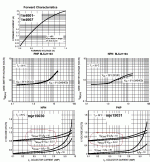
Below I've attached the junction voltage drop curves for your biasing diodes, the output transistors and the driver transistors.
With a VAS quiescent current of ~20mA each IN4001 diode will give you a little under 650mV bias voltage. You are looking at about 600mV for each driver and output power transistor, so a biasing voltage of over 2.4V will be required to develop a standing voltage in the power transistors for class AB operation. Three diodes will give less than 2V.
With a VAS quiescent current of ~20mA each IN4001 diode will give you a little under 650mV bias voltage. You are looking at about 600mV for each driver and output power transistor, so a biasing voltage of over 2.4V will be required to develop a standing voltage in the power transistors for class AB operation. Three diodes will give less than 2V.
Attachments
Re: Re: Re: 1000 Watt Sub Amp: Design / Build
Plenty of heatsink when used with a small quiet fan. It's about the same size I used in a CS800 clone, with two clamshelled together. It runs 1.4 ohms per side with 7xMJ21193/4 on +/-80v and never has to switch to full speed on the fans.
MJL21193 said:
I did a fair bit of research on heatsink requirements for this amp. Using this formula: Pd = (Vpp^2 )/(R(Load)*2 * PI^2 to determine total dissipation at full power I get 490 watts at 2 ohm load. Lotsa heat!
Here's the heatsink, with the 18 output devices laid out to see how they fit.
Plenty of heatsink when used with a small quiet fan. It's about the same size I used in a CS800 clone, with two clamshelled together. It runs 1.4 ohms per side with 7xMJ21193/4 on +/-80v and never has to switch to full speed on the fans.
Looks like an interesting project! I like the idea of so many output devices, seems much more solid . The heatsink looks to be designed mainly for convection cooling since the fins are large and quite well spaced but a fan should still increase its effectiveness a fair amount. How will you mount the semis? I'm going to use M3 allen head bolts on my new amp, but clamp mounting is my favourite where possible.
You'll need some really thick cabling and solid grounding, just how much current can you put through a normal copper clad board? I usually use them for my power rails (storage caps) and ground for amps (cuts to form 3 sections). A thicker piece of copper might be better at this power level.
. The heatsink looks to be designed mainly for convection cooling since the fins are large and quite well spaced but a fan should still increase its effectiveness a fair amount. How will you mount the semis? I'm going to use M3 allen head bolts on my new amp, but clamp mounting is my favourite where possible. You'll need some really thick cabling and solid grounding, just how much current can you put through a normal copper clad board? I usually use them for my power rails (storage caps) and ground for amps (cuts to form 3 sections). A thicker piece of copper might be better at this power level.
Thick copper would work, that's for sure. For 1000W @ 2 ohm he's probably needing the lowest resistance paths possible to handle the current!
When I built my 350W sub amp, I used thick wires and PTP (Point to Point) soldering on the power devices and drivers because of the high currents. I used the PCB only for the lower current VAS and differential stages, then used this circuit to "drive" the output stage.
When I built my 350W sub amp, I used thick wires and PTP (Point to Point) soldering on the power devices and drivers because of the high currents. I used the PCB only for the lower current VAS and differential stages, then used this circuit to "drive" the output stage.
MJL21193 said:
Hi EWorkshop1708,
The problem with raising the VAS current in the present configuration, is that idle current will also increase. The VAS is running with ~12mA right now. I'd like to increase it - up to 20mA or more (the device can handle it), but that means either removing one diode and let the amp run B or ditch the diodes and use a Vbe multiplier.
You can put a resistor in parallel across the diodes to drop the idle current, and have a higher VAS current.
G.Kleinschmidt said:
An opamp based low pass filter preamp with selectable turnover frequencies and roll off slope for this amplifier would also be something to look into.
PS, with a 1kW subwoofer amplifier I’m glad you’re not my neighbour.
Hi Glen,
Thanks for your interest here. This amp will get signal from the Linkwitz transform which is fed from the subwoofer output from my X-Fi extreme audio sound card. This sub is almost exclusively for home theater, with my HTPC being the source.
Come now! I think we would get along well as neighbours.

Besides, it's only 1kw at 2 ohms, a meager 500 watts at 4. Didn't you build a 1kw class A Amp?

G.Kleinschmidt said:Also, looking at your circuit a little closer, I think that more than three diodes would be required for class AB operation in real life and much larger emitter resistors will be needed for the output pairs.
I'm scrapping the diodes in favour of a Vbe multiplier - more room for adjustment. Less hassle mounting a TO-220 to the heatsink than three diodes.
The .1 ohm emitter resistors is leftover from when this amp design was class B, I just didn't think to change these.
Fact is I don't have enough 5 watt emitter resistors of any value on hand to complete this, so I'll be picking up some more. Could go .33 ohm, like is in my P68.
G.Kleinschmidt said:Below I've attached the junction voltage drop curves for your biasing diodes, the output transistors and the driver transistors.
With a VAS quiescent current of ~20mA each IN4001 diode will give you a little under 650mV bias voltage. You are looking at about 600mV for each driver and output power transistor, so a biasing voltage of over 2.4V will be required to develop a standing voltage in the power transistors for class AB operation. Three diodes will give less than 2V.
Like I said above, I'll be going with a Vbe bias, but thanks for the info.
Multisim doesn't realistically simulate Vbe (due to inaccurate models, like you say?), as I've found before. The values for the resistors in the bias servo in the simulation doesn't give the correct results in the real circuit. To simulate is one thing, but to get the actual values I need to calculate. So, the values shown on the schematic now are for simulation only and will be changed to the correct ones in the actual amp.
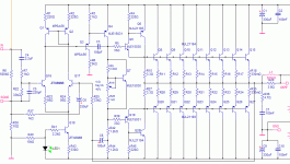
Here's an updated schematic. Includes the Vbe multi and the emitter resistor value changes. Also I've increased the VAS current to ~27mA.
Attachments
Re: Re: Re: Re: 1000 Watt Sub Amp: Design / Build
Hi wg_ski,
Yes I want to incorporate a temperature controlled fan that will stay off until the heatsink temp gets to ~70 degrees C. This may be insurance more than a requirement at the higher impedance.
I have been thinking about mounting the outputs on the heatsink and wiring them direct, without a board. Use 12 gauge solid copper wire for the rails and output. this would simplify things and I could put the rest of the circuit on a smaller board, with the drivers and the Vbe multiplier transistor on the outer edge to mount direct to the heatsink.
Another possibility is to cut the heatsink down the middle and direct couple the outputs to the sinks, using those as the voltage rails. This would mean having the sinks isolated from the chassis and moving them inside the case to avoid body contact with the potentially lethal voltage
That would mean I'd definitely need fans for cooling.
Possibilities!
wg_ski said:
Plenty of heatsink when used with a small quiet fan. It's about the same size I used in a CS800 clone, with two clamshelled together. It runs 1.4 ohms per side with 7xMJ21193/4 on +/-80v and never has to switch to full speed on the fans.
Hi wg_ski,
Yes I want to incorporate a temperature controlled fan that will stay off until the heatsink temp gets to ~70 degrees C. This may be insurance more than a requirement at the higher impedance.
Dr.EM said:Looks like an interesting project!
How will you mount the semis?
You'll need some really thick cabling and solid grounding, just how much current can you put through a normal copper clad board? I usually use them for my power rails (storage caps) and ground for amps (cuts to form 3 sections). A thicker piece of copper might be better at this power level.
I have been thinking about mounting the outputs on the heatsink and wiring them direct, without a board. Use 12 gauge solid copper wire for the rails and output. this would simplify things and I could put the rest of the circuit on a smaller board, with the drivers and the Vbe multiplier transistor on the outer edge to mount direct to the heatsink.
Another possibility is to cut the heatsink down the middle and direct couple the outputs to the sinks, using those as the voltage rails. This would mean having the sinks isolated from the chassis and moving them inside the case to avoid body contact with the potentially lethal voltage
That would mean I'd definitely need fans for cooling.
Possibilities!
EWorkshop1708 said:Thick copper would work, that's for sure. For 1000W @ 2 ohm he's probably needing the lowest resistance paths possible to handle the current!
When I built my 350W sub amp, I used thick wires and PTP (Point to Point) soldering on the power devices and drivers because of the high currents. I used the PCB only for the lower current VAS and differential stages, then used this circuit to "drive" the output stage.
Yes, this is what I had in mind. Pretty much a waste of a circuit board to mount that many devices.
What do you think of my idea to use the heatsinks as the rails? The more I consider it, the more I like it.
EWorkshop1708 said:
You can put a resistor in parallel across the diodes to drop the idle current, and have a higher VAS current.
Thanks! I didn't know this. One of the hazards of being a rookie.
MJL21193 said:
Yes, this is what I had in mind. Pretty much a waste of a circuit board to mount that many devices.
What do you think of my idea to use the heatsinks as the rails? The more I consider it, the more I like it.
It's fine, just don't touch the heatsinks during use
 Since you will have no thermal pad, there will be good thermal contact. It's a hassle to cut heatsinks however. Since it's a huge amp, your EF topology is fine.
 What I did on my amp was use CFP and no insulators, and the NPNs (+ PNP driver & silpad) on one heatsink, and the PNPs on the other sink. Since both sinks are near output potential, I get no shock, unless I touch ground and the heatsinks while the amp is playing loud.
- Status
- This old topic is closed. If you want to reopen this topic, contact a moderator using the "Report Post" button.
- Home
- Amplifiers
- Solid State
- 1000 Watt Sub Amp: Design / Build