How do you do this?
Just by comparing with the source, meaning that we can find a way to listen to the source with minimal amplification. Headphone is needed. If the amplifier output is recorded it can be used for comparison direct with the source.
I can sympathise with this view but I think it's dangerous to generalise.
Many years ago I built an amp with a similar o/p stage to the MMAMFM. It sounded dull. It put me off this topology. However the MMAMFM is anything but dull. Looks like my bias was wrong.
What is MMAMFM? Is it MMADFM?
I haven't seen anyone else made an upgrade to the JLH 30W. I believe you didn't mean the JLH (attached) that sounded dull?
Attachments
Hi Dave,
Quite so. It is verboten to generalise.
What do you think about the depth of image in your modded Mooly amp?
Hugh
I can sympathise with this view but I think it's dangerous to generalise.
Quite so. It is verboten to generalise.
What do you think about the depth of image in your modded Mooly amp?
Hugh
Just by comparing with the source, meaning that we can find a way to listen to the source with minimal amplification. Headphone is needed. If the amplifier output is recorded it can be used for comparison direct with the source.
What is MMAMFM? Is it MMADFM?
I haven't seen anyone else made an upgrade to the JLH 30W. I believe you didn't mean the JLH (attached) that sounded dull?
Para 1: Thanks for the clarification
Para 2: Same thing, sorry I muddled "made" and "designed"
Para 3: No, I think it was an amp of my own design. It was more than 20 years ago. I do remember replacing the CFP output stage with a LatFET source follower and it sounded a lot better.
Are you saying the JLW 30W sounds good... and by implication has good tonality? Doesn't that break your rule that CFP outputs sound "wrong"?
Hi Dave,
Quite so. It is verboten to generalise.
What do you think about the depth of image in your modded Mooly amp?
Hugh
I have to confess that stereo image is not high on my list of priorities and I don't really pay attention to it. However, yes it does seem to be significantly more 3D than before the mod.
As time has gone on I am finding that I have no inclination to swap to any of my other amps (currently I have a Leach, an Akitika, a MyRef and a very good KT88 amp sat on the floor).
The Mooly HD just sounds so damn right!
Doesn't that break your rule that CFP outputs sound "wrong"?
I have mentioned that most people don't even know what a correct tonality is. I mean, not everyone will be able to hear the difference. In other words, the difference almost doesn't exist. It doesn't exist for most people.
Not like you, I have never heard even one CFP amp that doesn't sound good. It's just when we look into fine detail among best amps that the difference surfaces.
The Mooly HD just sounds so damn right!
I'm glad to know that.
Long time ago I tried to improve Mooly amp but with no success. I didn't know anything about the art of compensation then. Now that I know this art, I have had a plan to try again. But I know for sure from studying AKSA amps that AKSA understands this art so he must have made the improvement.

so he must have made the improvement
John, this is a pig in a poke. BTW, saudara orang Indonesia atau orang barat? I have done so many little experiments that I have discovered a few of them. Compensation and fb regimes are absolutely at the bottom of this, and I have heard good and bad CFPs, I really don't think one or another configuration is tops.
The engineering was done sixty years ago. To improve the mousetrap we have to use psychoacoustics, and now I work almost exclusively with harmonic profiling.
Hugh
Last edited:
Hugh, you are the one who said the mod will bring the amp to another level. Why shouldn't I believe that. I haven't checked but i think it will also slightly increase the input cmmr?
Besides compensation/fb, I plan to try different transistors for the driver stage. Hard to find suitable transistor with sufficient Vceo but i will check if 50v is possible (with supply reduction if necessary). Also will see what happen if the 2N5551 (npn) is married with MPSA92 (pnp). Will try 'high end' opamp for the servo too.
Working with several amp prototypes right now.
I think there is still to be done, especially when the output transistor is a latfet. I have found a topology suitable to drive latfet, but am reluctant to invest time on it. Not a priority right now. Almost any topology can be special if we invest time on it, right?
Besides compensation/fb, I plan to try different transistors for the driver stage. Hard to find suitable transistor with sufficient Vceo but i will check if 50v is possible (with supply reduction if necessary). Also will see what happen if the 2N5551 (npn) is married with MPSA92 (pnp). Will try 'high end' opamp for the servo too.
Working with several amp prototypes right now.
The engineering was done sixty years ago. To improve the mousetrap we have to use psychoacoustics, and now I work almost exclusively with harmonic profiling.
I think there is still to be done, especially when the output transistor is a latfet. I have found a topology suitable to drive latfet, but am reluctant to invest time on it. Not a priority right now. Almost any topology can be special if we invest time on it, right?
Its interesting hearing your thoughts and comments. The only reason (if your wondering ") ) that I haven't tried Hugh's mod is simply that it would be a major dismantling exercise as each power amp is in its own tightly screwed together 'case'/subassembly.
) that I haven't tried Hugh's mod is simply that it would be a major dismantling exercise as each power amp is in its own tightly screwed together 'case'/subassembly.
The specified opamp (a genuine TL071 type) is guaranteed to work correctly on the designs single -12 volt rail.
) that I haven't tried Hugh's mod is simply that it would be a major dismantling exercise as each power amp is in its own tightly screwed together 'case'/subassembly.The specified opamp (a genuine TL071 type) is guaranteed to work correctly on the designs single -12 volt rail.
Attachments

... and now I work almost exclusively with harmonic profiling.
Hugh
Have you seen this?:
Katz's Corner Episode 25: Adventures in Distortion | InnerFidelity
Mooly,
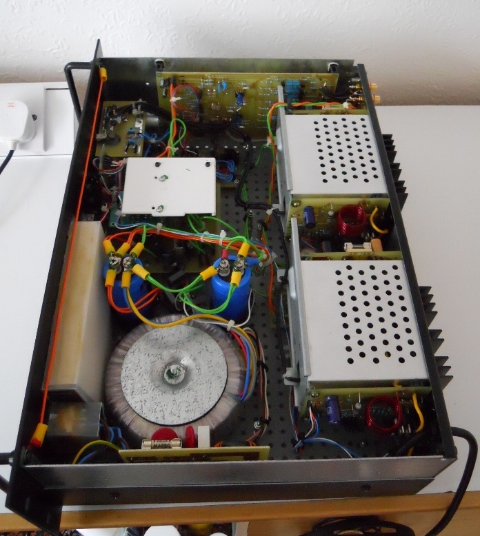
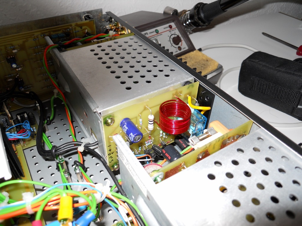
In a second I thought it was the amp pcb outside the cage. So you put the output coil in the protector pcb.
The sub casing looks like a faraday cage. I don't know how to design a faraday cage yet but i plan to use it everywhere in my amp. In the past i just used random shape more or less like your sub case.
At audio frequencies, a "Faraday Cage" is simply metal sheet. The holes you see in Mooly's pic are for cooling air circulation and don't form part of any design relating to Faraday's discovery. At VHF and higher frequencies, we can consider the hole or mesh size to be important and subject to appropriate design.
Sure, people like to use important sounding names to be cool but you don't have to design anything. If we need to shield our audio gear from EMI, RFI etc. we simply enclose it in a suitable size, grounded metal box as radio, audio etc. manufacturers and serious DIYs have done for around 100 years.
Sure, people like to use important sounding names to be cool but you don't have to design anything. If we need to shield our audio gear from EMI, RFI etc. we simply enclose it in a suitable size, grounded metal box as radio, audio etc. manufacturers and serious DIYs have done for around 100 years.
Have you seen this?:
Katz's Corner Episode 25: Adventures in Distortion | InnerFidelity
No, Dave, I hadn't seen it. But after reflection it really affirms the direction I started to take about ten years ago. I'm pleased; I may be on the right track. After all, Bob Katz has a huge following......
Thanks for the link. Compulsory reading for OCD audiophiles like us.....
Hugh
Sure, people like to use important sounding names to be cool but you don't have to design anything. If we need to shield our audio gear from EMI, RFI etc. we simply enclose it in a suitable size, grounded metal box as radio, audio etc. manufacturers and serious DIYs have done for around 100 years.
I think interference (EMI, RFI, 50/60Hz or whatever it is) is serious issue in high quality audio.
In an amplifier box you can find transformer or worse switching supply. Often the sound of an audio device is better when the top casing is off (something that I couldn't explain). Metal can LME49720/LM4562 is known to sound better than the plastic case (may be just the temp but who knows).
Hello Mooly,
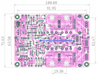
If a 2U case such as the one (dissipante) available from diyaudio store to be used, the width of PCB needs to be less than 80mm. This got me thinking that I need to reduce width at the same time keep the length to less than 100 mm to take advantage of PCB costs from China. Many compromises had to be made to achieve this.
So I came with the attached plan of layout, by reducing component package options . It would be challenging to fit components and solder them, but should be doable if care is taken and properly planned. Test and measuring would be critical too with compact layouts (no shaky hands).
600mW resistors can now be similar to https://www.mouser.in/datasheet/2/447/Yageo LR_MF0_2013-775182.pdf with 6.8mm length, 2.6mm dia, 1%, with TCR of 50ppm can be easily fitted. Power resistors can be BPR58 low-inductive current sense series.
I have a few queries, would be grateful if you could answer them.
1. if one were to use 45V psu, is the distance between the o/p pair ok for proper dissipation? My thinking was that, 2 pairs mean a larger area of contact in which to dissipate the heat so would be ok.
2. If fitment of decoupling caps between the mosfets is too inconvenient, can they be fitted at the supply input and ground (see additional pads provided provided near -45V and GND connectors and also near +45V and C9) and hung off board horizontally? In order to isolate these caps from heat of the heatsink, some thick foam tape could be used on the heatsink. 105 Deg. parts preferred here.
3. For the long term durability, do you feel that one needs to replace the trimmer with appropriate resistor? You had it mentioned some where on the thread I think, I cant find it again. I am not so sure if read and understood it correctly.
regards
Prasi
Attachments
Prasi,
I absolutely laud your efforts in trying to optimize PCB sizing in order to make it cost effective as possible for the DIY enthusiast to undertake such projects. On the other hand isn't the PCB cost only a small part of the total outlay in actually building an amplifier?
I am making this post NOT to offend or criticize the hard work folks like you do for FREE for the DIY community - it is rather to make a point for folks like us who buy the PCBs for the group buys, that we should focus on the total cost and not only on the PCB. I would rather pay a little more for the PCB if the form factor allows easy assembly and it's possible to use with more widely available /low cost chassis.
This project is a good example of such a case - the 100 mm x 100 mm PCB would require a 3U chassis, whereas a 50mm x 200 mm PCB can fit into a slimmer 2U chassis if thermal characteristics of the amp allow that. The 50mm x 200mm PCB size is just a stated dimension, I am not claiming that it would be possible to do a good design using those exact dimensions - that is for the layout artists like Prasi to decide on.
I have stated my understanding / point of view, would love to hear from other folks.
Last edited:
two or 3 things
1. There are many people who still do home etched PCBs, so thats why single sided design is maintained and pdf's are posted. Not all people have time and resources for group buys OR manufactured PCBs.
2. less than 100mm length allows people order PCBs for themselves individually without having to depend on anyone else or the GB to go through.
3. 2U case is considerably cheaper and widely available especially old amps or from scrap dealers, old instrument cases etc.
first design is 2 pair o/p > 100mm length and 3U case
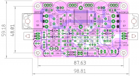
second one is 1 pair o/p <100 mm length and 3U case
third one is 2 pair o/p <100mm length and slimmer width (vetting by designer awaited)
I purposefully designed them such that all three can be done at home without having to depend on manufactured PCBs either through GB or individually.
I think people love choices to see what they have and what can be used from existing stock and existing chassis.
Also, with many guys, there is no need for buying components every time (no bom required for every amp) or Chassis is already available fitted with some other diy amp. There will be all the parts already in their bin (this design doesn't call for any special parts). So the "total cost" actually doesnt matter for such people as everything is already available at home.
1. There are many people who still do home etched PCBs, so thats why single sided design is maintained and pdf's are posted. Not all people have time and resources for group buys OR manufactured PCBs.
2. less than 100mm length allows people order PCBs for themselves individually without having to depend on anyone else or the GB to go through.
3. 2U case is considerably cheaper and widely available especially old amps or from scrap dealers, old instrument cases etc.
first design is 2 pair o/p > 100mm length and 3U case
second one is 1 pair o/p <100 mm length and 3U case
third one is 2 pair o/p <100mm length and slimmer width (vetting by designer awaited)
I purposefully designed them such that all three can be done at home without having to depend on manufactured PCBs either through GB or individually.
I think people love choices to see what they have and what can be used from existing stock and existing chassis.
Also, with many guys, there is no need for buying components every time (no bom required for every amp) or Chassis is already available fitted with some other diy amp. There will be all the parts already in their bin (this design doesn't call for any special parts). So the "total cost" actually doesnt matter for such people as everything is already available at home.
Last edited:
Hello Mooly,
If a 2U case such as the one (dissipante) available from diyaudio store to be used, the width of PCB needs to be less than 80mm. This got me thinking that I need to reduce width at the same time keep the length to less than 100 mm to take advantage of PCB costs from China. Many compromises had to be made to achieve this.
So I came with the attached plan of layout, by reducing component package options . It would be challenging to fit components and solder them, but should be doable if care is taken and properly planned. Test and measuring would be critical too with compact layouts (no shaky hands).
600mW resistors can now be similar to https://www.mouser.in/datasheet/2/447/Yageo LR_MF0_2013-775182.pdf with 6.8mm length, 2.6mm dia, 1%, with TCR of 50ppm can be easily fitted. Power resistors can be BPR58 low-inductive current sense series.
I have a few queries, would be grateful if you could answer them.
1. if one were to use 45V psu, is the distance between the o/p pair ok for proper dissipation? My thinking was that, 2 pairs mean a larger area of contact in which to dissipate the heat so would be ok.
2. If fitment of decoupling caps between the mosfets is too inconvenient, can they be fitted at the supply input and ground (see additional pads provided provided near -45V and GND connectors and also near +45V and C9) and hung off board horizontally? In order to isolate these caps from heat of the heatsink, some thick foam tape could be used on the heatsink. 105 Deg. parts preferred here.
3. For the long term durability, do you feel that one needs to replace the trimmer with appropriate resistor? You had it mentioned some where on the thread I think, I cant find it again. I am not so sure if read and understood it correctly.
regards
Prasi
There should be no thermal problems as long as the heatsink is sufficient. For normal use (music) the single output pair amp runs very cool. A dual pair will run hotter due to doubling up of the static dissipation.
The decoupling looks OK and you can always mount small caps under the board.
Trimmers can be a problem for long term reliability and particularly where relatively large currents flow in them. Although the VAS current would be within the spec of many trimmers my personal recommendation is to always replace with a fixed value part.
Hello Prasi,
I have one question about all these PCB : why every body put the power transistors completely under the PCB ?
As you know I have decided to build the Quasi (an other amplifier) but as I wanted to put it in a very low profile chassis even smaller than the 2U dissipante : Boitier DIY 100% Aluminium avec dissipateur thermique 271x226x70mm - Audiophonics . I redesigned the PCB because the four others, including yours, were too big. To keep the PCB small enough, to have a better cooling and an easy mounting, I put half part of the power transistors outside of the board
One other possibility to keep vertical size small is to put the power transistors on left and right side of the PCB instead of top and bottom side, this will also improve cooling since they will be more space between them and the bottom transistors are actually warming up the top ones
An other way to save space could be to remove fuse that can be fitted on an external protection module with a DC protection relay.
As an example of these modifications, I show the PCB that you kindly improved for me
Regards,
Marc
Attachments
Hello Marc,
If one has an idea of the actual case and heatsink, then a better custom PCB can be designed considering mechanical constraints, such as your case of quasi complimentary amp as you already knew what case and which heatsink.
Remember, quasi is double sided, whereas this one is single sided. So, simplest layout with minimal jumpers and with minimal trace lengths is priority and it also depends on circuit complexity, type of components and number of o/p transistors.
Fuses: I place them on amp PCB or PSU PCB, to minimize wiring and connectors.
If something very specific is required by someone, then there is always the link given in my signature.
regards
prasi
If one has an idea of the actual case and heatsink, then a better custom PCB can be designed considering mechanical constraints, such as your case of quasi complimentary amp as you already knew what case and which heatsink.
Remember, quasi is double sided, whereas this one is single sided. So, simplest layout with minimal jumpers and with minimal trace lengths is priority and it also depends on circuit complexity, type of components and number of o/p transistors.
Fuses: I place them on amp PCB or PSU PCB, to minimize wiring and connectors.
If something very specific is required by someone, then there is always the link given in my signature
.regards
prasi
- Home
- Amplifiers
- Solid State
- My MOSFET amplifier designed for music