'm really not clear what is intended of coil purpose...
Belt and braces approach to ensure absolute stability as was common practice at the time. The 0.22 ohm series output resistor alone is probably sufficient without the coil, however the original has them and it works and works well
")
To add some numbers to this...
Without an inductor and into a non-capacitive resistive load, you get 27 db and 83 degrees of margin.
Add a 100n capacitive load and this drops to 6db and 79 degrees.
Put a 1uH inductor in and it brings it back to 27db and 76 degrees.
Now, 1 meter of 14 gauge wire has a self-inductance of 1.4uH, so you're likely OK without it. But as Mooly points out, belts and braces for some extra security.
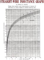
Its in uH. Here's a chart from the February 1966 edition of Electronic World. However, this is for a straight single wire. In practice, the output would be ran alongside the ground and possibly twisted which would reduce self-inductance.
There's numerous calculators online such as this one: Wire Self Inductance Calculator. The formula is fairly complex, so using a calculator makes life easier.
There's numerous calculators online such as this one: Wire Self Inductance Calculator. The formula is fairly complex, so using a calculator makes life easier.
Attachments
Did some drilling and tapping today, to assemble the main ''engine block''. The empty veroboard on top will be populated with the output inductors, protection circuit, and rail fuses.
Afterwards I have noticed that the remaining space in the case is somewhat tight to fit in the original PSU that I wanted to use. I think I can use some parts that were intended for another project instead.


Afterwards I have noticed that the remaining space in the case is somewhat tight to fit in the original PSU that I wanted to use. I think I can use some parts that were intended for another project instead.
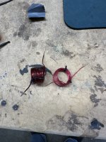
Data:
7/8” inside diameter mandrel.
Wire dia .047, 12 coils = 2.96uh, .03R
Wire dia .036, 12 coils = 3.27uh, .08R
Wire dia. .08, 12 coils = 1.92uh, .02R
Wire dia. .047, 20 coils = 5.88uh, .035R
7/8” inside diameter mandrel.
Wire dia .047, 12 coils = 2.96uh, .03R
Wire dia .036, 12 coils = 3.27uh, .08R
Wire dia. .08, 12 coils = 1.92uh, .02R
Wire dia. .047, 20 coils = 5.88uh, .035R
Attachments
Last edited:
This is quite useful: https://www.circuits.dk/calculator_single_layer_aircore.htm
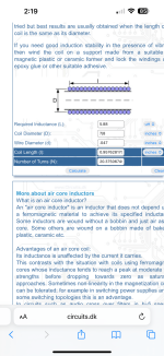
It is... but remember any changes made are deviations from the original design and have not been verified.I see 5-6uH has been suggested but this seems to be quite a large value compared to other designs.
For a CFP type input stage, this is the correct range of the till coil at the amplifier output. For this type of output stage, I got similar results, only this coil needs to be shunted with a low-resistance resistor, which is not in the circuit and this is an error, because no initial current flows through the coil, so it must be shunted for linearity in the audio signal circuit.How large an inductor do we need on the output?
I see 5-6uH has been suggested but this seems to be quite a large value compared to other designs.
For current protection of the Mosfet, wirewound resistors with a nominal value of 0.22 ohms are usually installed in the drains; if there is a speaker protection unit at the output with a turn-on delay, it can also be sufficient to protect against a short circuit in the load.Speaker protection (turn-on delay + output voltage offset detection) will protect your speakers from damage but is any overcurrent protection necessary to prevent accidental shorting of the amplifier output to ground from blowing the output MOSFETs?
It is necessary to protect the NFB circuit from the capacitive nature of the impedance of the speaker system (this is the area where the impedance decreases with increasing frequency).I'm really not clear what is intended of coil purpose...
Speaker protection (turn-on delay + output voltage offset detection) will protect your speakers from damage but is any overcurrent protection necessary to prevent accidental shorting of the amplifier output to ground from blowing the output MOSFETs?
I did not include any over current protection beyond rail fuses because at the time this was designed and built I never envisaged anyone but myself ever building this. If I short the output and blow it up that is my fault alone
For a CFP type input stage, this is the correct range of the till coil at the amplifier output. For this type of output stage, I got similar results, only this coil needs to be shunted with a low-resistance resistor, which is not in the circuit and this is an error, because no initial current flows through the coil, so it must be shunted for linearity in the audio signal circuit.
The omission of the damping resistor across the coil on the original hand drawn diagram has been mentioned and covered several times in the thread over the years and is actually mentioned in point '1' in post #1
To protect against the short circuit, presumably it will be necessary to sense the induced voltage across the 0.22 ohm drain resistors. What max current should the protection circuitry (I'll be using the Hifisonix speaker protection circuit) be set to trip at? Exicon EX10N20/P20 laterals have an Id max of 8A and a max dissipation of 125WFor current protection of the Mosfet, wirewound resistors with a nominal value of 0.22 ohms are usually installed in the drains; if there is a speaker protection unit at the output with a turn-on delay, it can also be sufficient to protect against a short circuit in the load.
The main thing is that don’t forget to put it.he omission of the damping resistor across the coil on the original hand drawn diagram has been mentioned and covered several times in the thread over the years and is actually mentioned in point '1' in post #1
the value of this resistor is determined based on the parameters of the compensation circuit in the feedback circuit of the amplifier and
for a Till coil with a nominal value of 4 uH, the resistor is 8.2 Ohms,
for 5 uH the resistor is 10 ohms,
for 6 uH the resistor is 12 ohms.
If these circuit ratings are not enough to protect the transients in the amplifier, then you will most likely need to limit the spectrum at the amplifier input.
Last edited:
- Home
- Amplifiers
- Solid State
- My MOSFET amplifier designed for music