Here is one of them:
http://www.diyaudio.com/forums/solid-state/169590-mongrel-supersym-ii-8.html#post2277473
EDIT:
This one, a few posts later, shows you all the crazy stuff you can do:
http://www.diyaudio.com/forums/solid-state/169590-mongrel-supersym-ii-8.html#post2277539
However, if you want to use the CFP I think you want to have room to put in a snubbing resistor in series with one of the caps (most probably the shunt cap) say 22R or thereabouts, because the CFP multiplier can oscillate. As far as this goes, it is up to your own experimentation.
- keantoken
Last edited:
Here are some more posts:
http://www.diyaudio.com/forums/aksa/152031-aspen-headphone-amp-7.html#post1943817
http://www.diyaudio.com/forums/aksa/152031-aspen-headphone-amp-7.html#post1944472
http://www.diyaudio.com/forums/solid-state/169590-mongrel-supersym-ii-7.html#post2276372
This should all be helpful in making Vbe multiplier decisions (outside of thermal considerations).
- keantoken
Last edited:
Thank you for this advices. By post #1 aboutHere are some more posts:
http://www.diyaudio.com/forums/aksa/152031-aspen-headphone-amp-7.html#post1943817
http://www.diyaudio.com/forums/aksa/152031-aspen-headphone-amp-7.html#post1944472
http://www.diyaudio.com/forums/solid-state/169590-mongrel-supersym-ii-7.html#post2276372
This should all be helpful in making Vbe multiplier decisions (outside of thermal considerations).
- keantoken
http://www.diyaudio.com/forums/solid-state/163489-accuphase-clone.html
there is an other variation again:
two diodes in series to the emitter line of Vbe transistor.
Last edited:
Thank you for this advices. By post #1 about
http://www.diyaudio.com/forums/solid-state/163489-accuphase-clone.html
there is an other variante again:
two diodes in series to the emitter line of Vbe transistor.
The same suggests B. Cordell in his book.
Most designers treat the Vbe multiplier's impedance as negligible. However a small electrolytic shunting one will only cover the treble and maybe midrange. While I have no subjective experience here, there seems to be a consensus that you want impedances in an amplifier to be flat through the audio range.
The two diodes will work for thermal considerations but will (estimating) drop the impedance by about 1/3.
- keantoken
The two diodes will work for thermal considerations but will (estimating) drop the impedance by about 1/3.
- keantoken
The cap in the feedback loop has different requirements depending on the feedback loop resistance, so it is not a good reference.
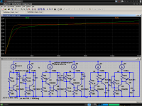
Here are two simulations. The first steps the value of the shunt capacitor between the values of 22u, 47u, 100u, 220u, 470u, 1000u. We can see that for both multipliers, you need an enormous shunt cap to cover the audio band.
The second shows a way to use a smaller cap to decouple the first resistor. Values simulated are 100n, 1u, 10u, 100u. The effect can cover the whole audio range with a reasonably sized cap, but the impedance of the multiplier will be larger than it would with the shunt cap. For comparison a 22uF shunt cap is included in this simulation to show the qualitative difference. With the shunt cap, impedance is less but only in the treble region. Because of the low Ib of Q5, the divider network resistance for the second multiplier can be increased by a decade, and this makes the cap trick 10 times better; now a small film cap could be used.
- keantoken
Attachments
The cap in the feedback loop has different requirements depending on the feedback loop resistance, so it is not a good reference.
Here are two simulations. The first steps the value of the shunt capacitor between the values of 22u, 47u, 100u, 220u, 470u, 1000u. We can see that for both multipliers, you need an enormous shunt cap to cover the audio band.
The second shows a way to use a smaller cap to decouple the first resistor. Values simulated are 100n, 1u, 10u, 100u. The effect can cover the whole audio range with a reasonably sized cap, but the impedance of the multiplier will be larger than it would with the shunt cap. For comparison a 22uF shunt cap is included in this simulation to show the qualitative difference. With the shunt cap, impedance is less but only in the treble region. Because of the low Ib of Q5, the divider network resistance for the second multiplier can be increased by a decade, and this makes the cap trick 10 times better; now a small film cap could be used.
- keantoken
I'm using your #2 CFP Vbe now on all my EF2 amps ... very stable. I'm using 100n and 10u for the caps. Highly recommended , I won't go back to the 1 device Vbe ... nope.
") Also , much easier to change coefficient for different heatsinks and output devices. The PNP device on the PCB of the 2 transistor version (npn is on the heatsink) also adds the coefficient of the case/room to the Vbe. Cold morning to a VERY hot day , this Vbe is VERY accurate.
Also , much easier to change coefficient for different heatsinks and output devices. The PNP device on the PCB of the 2 transistor version (npn is on the heatsink) also adds the coefficient of the case/room to the Vbe. Cold morning to a VERY hot day , this Vbe is VERY accurate. OS
I'm happy to hear about my ideas in service and doing well.
As if to spite me, I did a transient analysis (as opposed to AC) of the last image I posted, and discovered the first multiplier oscillating! Hell, I'm discovering anything can oscillate, even a current mirror (in real life). I suppose the question is not whether you're paranoid - but whether you're paranoid ENOUGH! *grumbles incoherently*
Have you thought about Hfe/Ib tempco? If a low gain transistor is used for the multiplier, this might change things up. Is it possible that the Ib tempco of the multiplier may compensate for the Ib tempco of the outputs/drivers through the base stoppers? With some math, one could adjust the divider impedance... I haven't tried this in simulation, but thermally accurate models would be necessary.
Also, as per my last post you might try increasing R101/R102 by a decade, along with the trimmer... Probly doesn't matter though...?
- keantoken
Hfe/Ib tempco.
I did figure that out. A sc3503 is not a perfect match for the NJW0281/0302 , but a mje340 is. The 3503 is a better match for my sankens. But one can "fine tune" the tempco with the right ratio of current passing through the PNP vs. what passes through the NPN's divider (the resistors). Could not simulate this , had to actually sub the devices on the real amp to come to these choices.
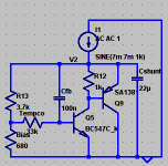
PS - even without C9 above , the circuit will not oscillate ... but I am paranoid. C9 also acts as a "stopper" (like in Rod elliots CFP output stage) quenching any stray parasitic's which could occur with the NPN sensor out on longer leads.
OS
I did figure that out. A sc3503 is not a perfect match for the NJW0281/0302 , but a mje340 is. The 3503 is a better match for my sankens. But one can "fine tune" the tempco with the right ratio of current passing through the PNP vs. what passes through the NPN's divider (the resistors). Could not simulate this , had to actually sub the devices on the real amp to come to these choices.
PS - even without C9 above , the circuit will not oscillate ... but I am paranoid. C9 also acts as a "stopper" (like in Rod elliots CFP output stage) quenching any stray parasitic's which could occur with the NPN sensor out on longer leads.
OS
Last edited:
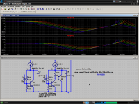
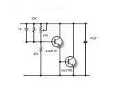
OS, I just realized it would be simple to just put another trimmer in series with the base of the NPN and set the divider resistance at a reasonably low value.
My idea is attached. Tempco can be adjusted without affecting the quiescent currents of the transistors. This way one can always use a set of transistors known to not oscillate.
- keantoken
My idea is attached. Tempco can be adjusted without affecting the quiescent currents of the transistors. This way one can always use a set of transistors known to not oscillate.
- keantoken
Attachments
Yes , that would work. It is essentially the same as changing the fixed resistor's values(without changing the current). Some would see it as too much trouble to have 2 Vbe adjustments. However... having this setup to use in a prototype would allow one to really fine tune for the final thermal solution.
OS
It is essentially the same as changing the fixed resistor's values(without changing the current). Some would see it as too much trouble to have 2 Vbe adjustments. However... having this setup to use in a prototype would allow one to really fine tune for the final thermal solution.OS
Last edited:
That circuit will do the job, but not much better than a single-transistor multiplier. Furthermore, if the trimmer disconnects, the output stage will be left at highest bias, which is not good. This is why it is safer to use the lower resistor as the trimmer.
I feel pretty awkward discussing the details of Vbe multipliers when all indications are that they are almost the least important part of an amplifier. Generally if you wanted to improve an amplifier I expect you would not worry about the multiplier.
If you want the "all-out" best Vbe multiplier in my opinion, the one shown in post 34 is the best. You may remove the Tempco trimmer if you want, it is there for fine-tuning the thermal response of the output stage. If you want to adjust using both trimmers, here is my suggested procedure:
1: Set Bias for the correct output bias voltage.
2: Drive the amp at a moderate power to heat up the output stage, for 30 minutes to an hour, then measure the output bias.
3: If the bias has increased, decrease the Tempco trimmer. If bias has decreased, increase the Tempco trimmer. Then readjust Bias to get the right output bias level.
4: Repeat starting at step 2 until the amp is properly thermally compensated. It will be faster if you keep notes on your measurements so you will know how much to turn the trimmer instead of guessing.
- keantoken
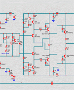
The inclusion of the "current-compensation" resistor (in single-transistor circuit) causes VCE to decrease when the input current increases. With the choice of resistor value the steepness of VCE limiting can be controlled. In essence, the value of should be optimized so that only slight voltage variations occur around the optimal bias voltage setting.
With the addition of another transistor (usually in the form of Sziklai pair) the loop gain of the VBE multiplier circuit can be increased. The first transistor serves as the temperature sensor while the second transistor amplifies its effect. The technique can reduce the resistance slope (U versus I) of the multiplier but substantial results are gained (again) only after the inclusion of current-compensation resistor. The advantages are a high linearity regardless of input current and a broader tolerance for values of current compensation resistor.
The results of using various configurations follow approximately the curves shown in the attachment. The linear the curve is, the better. The Sziklai pair can provide very linear performance but unfortunately it is extremely unstable. Using Miller capacitance can compensate the poor behaviour somehow but this is just a band-aid.
I don’t like the 2-transistor configuration because any instability in bias servo can have dreadful consequences. The single-transistor with current compensation works well although its behaviour depends a lot on device parameters such as beta.
I don’t know about FETs and MOSFETs but I remember something along the lines that they are used with MOSFET output transistors because of their somewhat better parameter matching with those than what the ordinary BJTs have. I could be wrong, though.
I assume, that this curves are appropriate to commonly used values of emitter resistors of the output power buffer pair (approximately 0R22 until 0R33)
What happens, if the mentioned emitter resistor values in the aera arround 1R and 2R (often to find by amps, where a great ammount of BjT power devices worked in parallel)?
I have heard that from a certain amount of emitter resistance value such Vbe multiplier no longer necessary. Instead this only a variable trimm resistor like by the use of audio MOSFETs and parallel switched capacitor comes in use.
Who knows this resistance value ??
Last edited:
- Home
- Amplifiers
- Solid State
- Differences between various vbe multipliers