Have read a few threads about both Circlotrons and IGBT. Have also had an idea for long about a transformer-coupled hybrid, with as much tube-like configuration as possible.
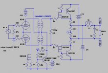
As IGBTs seems to be unsuitable for audio I got the idea of making them from a PNP-power BJT and a depletion MOSFET. This way one can bias the FET higher and thereby maybe make the two transistors work better. The DN2540 has only 200p Ciss, that according to the data sheet is independent of Vds.
I have also added a bias cicuit to get some temperature compensation. The IT is a Lundahl 1635, 1+1:1+1.
The amp is still not built so the question is how it will work IRL?
Attachments
Hi Bogdan,
Off course the circuit is Circlotron. The twist of it is the output pair configuration. The way I look at it this is the closest to a tube output stage you can get, with transistors and no OPT.
Simmed peak-peak voltage is 40V/8ohm and 35V/4ohm. This would be in the ballbark of 25W/8ohm and 40W/4ohm.
Output impedance is ca 0,8ohm.
About temperature compensation I am not sure how to choose it? With the previous schematic you go from 25-125 degrees C with a change of 1A to 0,8A. If you add a diode-connected BD140 in series with the 33ohm(and adjust the Itrim) you go from 1A to 0,3A.
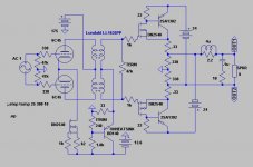
Did some more simming and also added a bipolar version, hope the link of the screendump is readable:
www.eflatjump.se/freqjfr.JPG
Also simmed distortion at 10k/20Vptp for comparision:
1 Bipolar pair: 1,26%
2 Mosfet: 1,16%
3 Depletionmosfet/bipolar pair: 0,26%
I am fully aware of that simmed distortion figures are not reliable as the transistormodels aren´t fully reliable. But to me the distortion figures , the frequency-response together with the temperature-stability points to that version 3 is interesting.
Still I also hope that the DN2540/2SA1302(NJL4302) pair sounds best.
Couldn't make out any of the real details in your screendump, but enough to see the general topology of what you're doing. It looks like your method has about 12dB less distortion. I wonder about the temperature stability too. Please keep us posted on your progress. I pointed out the depletion mode DN2540 a few years back, but no one expressed any interest in it.
 .
.revintage said:Did some more simming and also added a bipolar version, hope the link of the screendump is readable:
www.eflatjump.se/freqjfr.JPG
Also simmed distortion at 10k/20Vptp for comparision:
1 Bipolar pair: 1,26%
2 Mosfet: 1,16%
3 Depletionmosfet/bipolar pair: 0,26%
Now, wouldn't be interesting to see a bipolar/MOSFET sim? That is; a small signal driver and a power MOSFET!
I am actually using that combination with the components 2SA970/2SC2240 and 2SJ554/2SK2955. It is absolutely temperature stable - using 0.1//0.1 ohms = 0.05 ohms as Re. They are even used in a bridge configuration driving Quad ESL63. And there are no stability or temperature problems in my output stages. And it sounds good too.
I have only measured frequency linearity with sweeps and a RMS voltmeter and it is straight up to 20kHz (max. on CD ;-) . So IMHO this combination should not be dismissed.
But of course it depends on the type of MOSFETs.
I have only measured frequency linearity with sweeps and a RMS voltmeter and it is straight up to 20kHz (max. on CD ;-) . So IMHO this combination should not be dismissed.
But of course it depends on the type of MOSFETs.
- Status
- This old topic is closed. If you want to reopen this topic, contact a moderator using the "Report Post" button.
- Home
- Amplifiers
- Solid State
- Balanced compound-IGBT power amp idea