Hello,
Finished up an amp module of Randy Slones' Optimos design.
From what I am told, calculating Vbias is as attaining a quiescent current of 40mA.
I am using the Double Die Semelab devices and .5ohm RE or RMOS resistors. The calculation of Vq is as (40m) (.5+.5), or 40mV. Is this correct??
I ask because I am getting some distortion during medium volume playback. I would guess maybe at about the 100watt range, I get distortion when a sound like a heavy bass guitar or tom tom sound is played back. It is an awkward distortion to me because it appears to be coming out well before the module reaches it's power clip, and, the distortion seems to favor the midbass frequencies. The amp and power supply are capable of 220w at 8 and 300+w at 4 ohm. I am using ON and Fairchild semiconductors, 1% resistors etc...
I suppose the distortion could be a result of some other anomaly aside of Vbias adjustment, however, this is a good spot to start the questions.
Suggestions??
THX
Scott
I think you need some nice inputs from our friend Anthony Holton
www.aussieamplifiers.com
I hope he will suggest you soon with something good")
www.aussieamplifiers.com
I hope he will suggest you soon with something good
synonymous said:Finished up an amp module of Randy Slones' Optimos design.
From what I am told, calculating Vbias is as attaining a quiescent current of 40mA.
I am using the Double Die Semelab devices and .5ohm RE or RMOS resistors. The calculation of Vq is as (40m) (.5+.5), or 40mV. Is this correct??
It seems like at least a couple of things are funny. First of all, I know nothing about Sloan's design, but 40 mA is very low bias for these parts. The single-die LMOSFETs from Semelab have a zero tempco point of 120 mA, so the double-die parts should ideally be run at 240 mA. Below that point they will exhibit a positive tempco and the bias will not be stable.
I don't know where Sloan came up with 40 mA of bias. That is just silly. Increasing the bias past the zero tempco point will improve the sound quality, but you have to make sure that the heatsinking is up to the task of cooling the devices. This will largely depend on the rail voltages you are using.
I'm also not sure why you are measuring across *two* source resistors (0.5 + 0.5). The normal procedure is to have a single source resistor for each output device and measure across that source resistor. So it seems to me that you are really only running 20 mA of bias. This is 12 times lower than what I would recommend and could definitely cause distortion.
However, I would assume that the circuit also uses an overall feedback loop. This would tend to lessen the measured distortion, but not necessarily so much the audible distortion. Can you post a schematic?
Hey thanks,
I at one time had it measured out at up to 120 some mV and seemed to have better results audibly, but didn't trust my guesswork.
I am measuring across points equivalent to "TP3" and "TP4" on the schematic. I also am using the Semelab double die devices instead of the Hitachi as shown.
Of note, the following is verbatim from the project directions..
*R40, R41, R42, R43 / 5-watt, 5%, power resistor & Vbias settings
double die mosfet = .1 ohm @ 18mv VBias / 400 wpc
single die mosfet = .22 ohm @ 30mv VBias / 200 wpc
single die mosfet = ,5 ohm @ 50mv VBias / 200 wpc
However, in his book of projects he described it as 40mA target across the resistive value.
Big thanks for the reply
Scott
Attachments
I run Semelab/Magnatec BUZ901D/906D in a bass amplifier and can back Charles' statement that they need at least some 300mA (IIRC) bias each to sound good and keep the bias stable / slightly decreasing with increased temp.
National AppNote AN-1645 even states 180mA (found empirically) for the single die BUZ901/906 and contains useful graphs of bias vs. time after a load of 40W has been switched of (allowing to reach thermal equilibrium before switch-off, of course) which clearly show that the lowish 40mA will cause severe bias drift without further thermal compensation.
- Klaus
Scott, you write about "40mA target across the resistive value", sure about that exactly, I mean shouldn't it read 40mV instead of 40mA. And further, across which resistor value exactly?
From the values you gave in the cited table I read 100mA and 136mA resp. for single die and 180mA for double die.
- Klaus
From the values you gave in the cited table I read 100mA and 136mA resp. for single die and 180mA for double die.
- Klaus
Thanks,
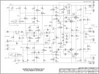
After wrestling a bit and learning of image and file size constraints I have uploaded the schematic image. Hopefully it is legible.
I wonder why such a large difference.
Hopefully this discussion will resolve the issue. I have made other modules in the past and had similar issues and always felt it were me or the parts. This could really crack the code.
THX
Scott
synonymous said:I wonder why such a large difference.
Probably a typo in Sloan's book. There are a lot of those in there.
The bias *voltages* you posted are much more reasonable. BUT these should be measured across only *one* resistor and not both. So what you want to do is measure from the test point to the speaker output, and *not* from test point to test point. (This should be done with no drive signal, of course.)
By the way, I would suggest going with a lower resistor value than 0.5 ohms. It appears from your posting that Sloan suggests 0.1 ohms for the double-die parts. This will work much better as long as you are using just one transistor per rail. If you are paralleling more than one, then you will have to try to match them no matter what value of source resistor you use. The lower the value of the resistor, the closer you will have to match them. But the lower the value of the resistor, the lower the distortion and the better the sound.
Correct,
I have one Pchannel and one Nchannel double die device in the module at this moment. I do this merely for testing purposes so as to only smoke one pair if it were to happen. Following the solution and test, I will be adding one more pair to bring the final tally to two pairs of the Semelab double dies, matching the schematic aside of the LMOSFET devices used.
I have one Pchannel and one Nchannel double die device in the module at this moment. I do this merely for testing purposes so as to only smoke one pair if it were to happen. Following the solution and test, I will be adding one more pair to bring the final tally to two pairs of the Semelab double dies, matching the schematic aside of the LMOSFET devices used.
... and the later the overcurrent protection kicks in. Which is good for the sound too, but maybe bad for those expensive lateralsCharles Hansen said:But the lower the value of the resistor, the lower the distortion and the better the sound...
- Klaus
Scott,
then I propose you should settle for the given bias point:
"double die mosfet = 0.1 ohm @ 18mV VBias / 400 wpc"
which also gives a reasonable operation point for the protection. Idle dissipation is also OK it seems, some 12 watts.
Take care while testing, at the moment you probably don't have overcurrent protection as you installed the outputs in the section where the testpoints are (quite silly design, these points should be where the protection circuitry is hooked).
Use test point 5 (output) and don't connect speaker lead.
- Klaus
synonymous said:So basically from what I have been reading is that the target from each resistor point to speaker output would read out as one +180mV and the other -180mV leaving one lead connected to speaker and using the other for testing the points? Correct?
No not at all. Where do you come up with these numbers???
You have already been given the correct bias when using a 0.1 ohm source resistor:
"double die mosfet = .1 ohm @ 18mv VBias / 400 wpc" (from your own post)
If you use a different resistor value, just scale the voltage. So if you have a 0.5 ohm resistor that is 5x that value, then the voltage should be 5x as great (remember Ohm's Law) at 90 mV.
"No not at all. Where do you come up with these numbers???"
Just trying to sift something from the previous posts.
I have a decent grasp of Ohm's Law, just don't trust my own speculation for something I take rather seriously. Granted that I am in diapers compared to the shakers here. I do greatly appreciate all the time and handy helper attitude others have shown me. Hopefully it will come back to those in some way.
Since the values I have shown you claim are as simple as applying Ohm's Law towards the resistance of the source resistors, would this apply to any amount of paralleled output devices??
THX again
I have tried all the values 240mV 180mV 90mV 18mV and a few others to no real good result. I cant say that there is much a difference in any of them.
Theoretically, is there a point at where you can rule out quiescent current as the culprit?? Generally is it a rule that of a quiescent current problem, more current resolves issues related?
Sorry for being an idiot
THX
Theoretically, is there a point at where you can rule out quiescent current as the culprit?? Generally is it a rule that of a quiescent current problem, more current resolves issues related?
Sorry for being an idiot
THX
No, you are not an "idiot". You are learning, as we all did. It's nice that now a community can help you.
I think it is safe to say that there must be some other problem with the amplifier besides the bias current. The best way to tell what is going on requires a lot of test equipment:
a) A signal generator -- this can be improvised with a CD player and a disc of test tones.
b) An oscilloscope to look at the waveforms.
c) A "dummy" load -- that is an 8 ohm (or so, anything between 5 and 15 ohms will do) resistor with a very high power rating (greater than the power of your amplifier. These are usually quite expensive -- around $50 for a 250 watt resistor. But you can go to Radio Shack and buy a 5 or 10 watt resistor and put it in a glass of water. This will handle quite a lot of power before the water heats up. Then just change the water.
If you don't have this, then the next best thing to do is to check all the voltages in the circuit. If it is a detailed construction project (like the Leach amplifier, for example) it should have a diagram showing the proper voltages at each point.
I have used a laptop (Powerbook) and some free or shareware sine generating software as well as a software scope. I used the audio out and audio inputs with connectors I made to do some rough debugging. This might be more than you can do at your level, I don't know, but if you are unsure then maybe don't try it. Search for such software. Last time I checked (few years ago) there were plenty of Mac versions out there. Probably more options if on a PC.
-SL
-SL
- Status
- This old topic is closed. If you want to reopen this topic, contact a moderator using the "Report Post" button.
- Home
- Amplifiers
- Solid State
- Vbias and Semelab Double Die LMOSFET