Battery as Power Source?
Hi Russ,
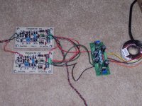
i am interested in building this amp, but would like something thats portable.
in the photo attatched to your post the setup is powered by 2 9v batteries. is this feasible as a permanent solution. how long do the batteries last, since its biased for class a i suspect not very long....
thanks, and cheers to a good design using readily available transistors!
Hi Russ,
i am interested in building this amp, but would like something thats portable.
in the photo attatched to your post the setup is powered by 2 9v batteries. is this feasible as a permanent solution. how long do the batteries last, since its biased for class a i suspect not very long....
thanks, and cheers to a good design using readily available transistors!
mymindinside said:Oops sorry, just read through your earlier posts,
you mentioned that one could run it from battery. Would any component values change based on an 18v battery supply?Two 9v batts in parallel
I think you mean in series
")
No no component changes at all, in fact thats how I first tested it. It works great.
Revision 1.1
I have updated the circuit to revision 1.1.
I simplified the CCS and Cascode voltage refences. This eliminates one transistor and makes it easier to use the same parts for different bias levels.
I also changes some component values to make transistor matching even less critical (it never was very critical), and to make the amp less prone to thermal runaway at high bias.
Suggested bias is to measure around 30mv at the emitter resistors (R1-R6). This will get you about 3ma bias per device. (9ma total) The amp will do fine well into about 60mv bias. The driver Qs will get a bit warm though.
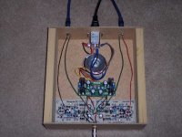
Here is a picture of my prototype of the Rev 1.1 layout.
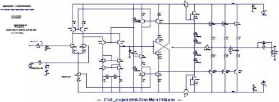
Schematics and PDS are in the zip file which can be found
HERE.
We will post a new BOM too.
Have fun!
:EDIT: Ignore the fact the the silk screen in the photo reads Version 1.0, its really 1.1
I have updated the circuit to revision 1.1.
I simplified the CCS and Cascode voltage refences. This eliminates one transistor and makes it easier to use the same parts for different bias levels.
I also changes some component values to make transistor matching even less critical (it never was very critical), and to make the amp less prone to thermal runaway at high bias.
Suggested bias is to measure around 30mv at the emitter resistors (R1-R6). This will get you about 3ma bias per device. (9ma total) The amp will do fine well into about 60mv bias. The driver Qs will get a bit warm though.
Here is a picture of my prototype of the Rev 1.1 layout.
Schematics and PDS are in the zip file which can be found
HERE.
We will post a new BOM too.
Have fun!
:EDIT: Ignore the fact the the silk screen in the photo reads Version 1.0, its really 1.1
Attachments
I got bored and did some simulation on this design tonight. It looks excellent. I used a 32R dummy load in my simulations, and included all optional components, except the output resistor/inductor. No parasitics were simulated. Here's the data:
Frequency response is ruler flat out to about 1MHz, -3dB at 10.46MHz. THD is 0.0007%, with the first harmonic at about -100dB. Slew rate is about 75V/uS (rise time to 2V is 27ns). There is a single cycle of ring on the rising edge of a 10KHz square wave, overshooting by about 0.2V above, recovering to 40mV below and settling immediately.
With a 1K load, THD improves to 0.0003% (-112dB first harmonic), and the settling behaviour with the square wave is a little nicer.
If anyone wants to see the plots I can generate them...
Looks like a very nice design Russ, thanks for sharing with the community!
Do you have any recommendations for SMD transistor substitutions? I guess BC850/860C would be appropriate, they seem to have the same specs?
I have used those as replacement for BC550C, BC560C.error401 said:Do you have any recommendations for SMD transistor substitutions? I guess BC850/860C would be appropriate, they seem to have the same specs?
Russ, it could be a good idea to have both TO92 and SOT23 pads
 I have it always
peranders said:
I have used those as replacement for BC550C, BC560C.
Russ, it could be a good idea to have both TO92 and SOT23 pads
Hello Peranders,
That is an excellent idea you have. I will give this a try. I have not done a lot of fully discrete PCBs yet, so this really had not crossed my mind.
I will have to think over how to execute the idea on a single side PCB. It may present some difficulty.
What I may do is offer an alternative SMT layout. For those so inclined.
Cheers!
Rus
error401 said:I got bored and did some simulation on this design tonight. It looks excellent. I used a 32R dummy load in my simulations, and included all optional components, except the output resistor/inductor.
Looks like a very nice design Russ, thanks for sharing with the community!
Do you have any recommendations for SMD transistor substitutions? I guess BC850/860C would be appropriate, they seem to have the same specs?
Hello,
You are very welcome, thanks for posting!
The SMT version of the 2N2222 and 2N2910 would work well in the design. Also there are many Qs from Zetex which work very well. really any low noise medium to high gain Q would be fine.
For the output Qs high gain is not required.
In other words, you could use BC550B or BC550C on the front end, and BC550A for the output Qs.
As for your simulations the sound spot on to me.
The output inductor/resistor helps clean up the square wave. You will notice the ringing is substantially reduced. I have listened to the amp with and without the inductor, and I personally find it better with it in place.Cheers!
Russ
Russ,
A variant on the diamond circuit you might like to think about is to bootstrap the power supply to the diamond transistors. In the standard circuit, it turns out almost the residual distortion is from the early effect, and bootstrapping removes that, bring the open loop distortion in simulations down to very low levels.
See here for a sample schematic.
I don't know if the improvement in output stage linearity would be worth the extra complexity, and if you might want to trade it for a simplification in some other area?
PigletsDad said:Russ,
A variant on the diamond circuit you might like to think about is to bootstrap the power supply to the diamond transistors. In the standard circuit, it turns out almost the residual distortion is from the early effect, and bootstrapping removes that, bring the open loop distortion in simulations down to very low levels.
See here for a sample schematic.
I don't know if the improvement in output stage linearity would be worth the extra complexity, and if you might want to trade it for a simplification in some other area?
Yes, I have actually considered bootstrapping, but in simulation I did not find the improvement that large, still I may have another look, as it could have been my fault in design.
I also tried ordinary CFP outputs, and Kulish cell type CFP outputs. Those gave the best simulations, but I wanted to keep the complexity down so I did not use them yet.
Cheers!
Russ
Russ White said:
Yes, I have actually considered bootstrapping, but in simulation I did not find the improvement that large, still I may have another look, as it could have been my fault in design.
I also tried ordinary CFP outputs, and Kulish cell type CFP outputs. Those gave the best simulations, but I wanted to keep the complexity down so I did not use them yet.
Cheers!
Russ
My simulations showing a big improvement were for a fairly lightly loaded stage, where the Early effect is probably the main culprit. It could easily be that once the current swing goes up, the advantage of removing the Early effect in the output devices gets swamped by the device current dependence.
Hi PiggletsDad,
I am very glad you mentioned this again, as I just simulated it again but only bootstrapping the input stage and the drivers (Outputs stay at rails). The results are very good! More than 50% reduction in THD at 20Khz!
Here what I did:
Harmonic Frequency Fourier Normalized Phase Normalized
Number [Hz] Component Component [degree] Phase [deg]
1 2.000e+04 1.989e+00 1.000e+00 -0.87° 0.00°
2 4.000e+04 1.566e-06 7.872e-07 139.57° 140.44°
3 6.000e+04 3.687e-07 1.854e-07 -120.96° -120.09°
4 8.000e+04 1.416e-07 7.117e-08 -162.15° -161.28°
5 1.000e+05 7.090e-08 3.565e-08 -82.70° -81.84°
6 1.200e+05 2.328e-09 1.170e-09 87.78° 88.65°
7 1.400e+05 3.302e-09 1.660e-09 -128.67° -127.80°
8 1.600e+05 1.874e-09 9.422e-10 73.57° 74.44°
9 1.800e+05 9.439e-10 4.745e-10 140.54° 141.41°
Total Harmonic Distortion: 0.000081%
Attachments
For reference here s the same circuit without the bootstrap.
Harmonic Frequency Fourier Normalized Phase Normalized
Number [Hz] Component Component [degree] Phase [deg]
1 2.000e+04 1.989e+00 1.000e+00 -0.85° 0.00°
2 4.000e+04 3.257e-06 1.637e-06 -2.56° -1.71°
3 6.000e+04 1.736e-07 8.729e-08 77.15° 78.00°
4 8.000e+04 7.050e-09 3.544e-09 -165.37° -164.52°
5 1.000e+05 1.294e-08 6.507e-09 84.07° 84.93°
6 1.200e+05 4.000e-09 2.011e-09 69.42° 70.28°
7 1.400e+05 2.326e-09 1.169e-09 -127.41° -126.56°
8 1.600e+05 3.547e-09 1.784e-09 -26.29° -25.44°
9 1.800e+05 1.779e-09 8.947e-10 -178.64° -177.79°
Total Harmonic Distortion: 0.000164%
- Home
- Amplifiers
- Solid State
- Diamante -a discrete medium power opamp