You need to take a break from watching You Tube. You also need to have a reference amplifier to know at any time, what it is that you are looking for - regardless of whether you are tired, ill, ears full of wax or in a bad mood etc.
Stupid is wandering about, listening to an ever-changing catalog of MP3 music recordings, believing in pseudo-science and imagining that we hear music through our PC speakers just as everyone else does. It's also stupid to design audio electronics by using the "pin the tail on the donkey" method and trying anything at all with component combinations until there is a distinct sound effect (maybe ka-boom!). OK, I may be exaggerating there")
Stupid is wandering about, listening to an ever-changing catalog of MP3 music recordings, believing in pseudo-science and imagining that we hear music through our PC speakers just as everyone else does. It's also stupid to design audio electronics by using the "pin the tail on the donkey" method and trying anything at all with component combinations until there is a distinct sound effect (maybe ka-boom!). OK, I may be exaggerating there
Hi ian , We are at a page of 431 at the moment in this thread, funny.
Hmmm, we can celebrate this with a TL431 shunt regulator This device can do many things.
Why TL431 is called TL431 ?
See, if you make a RL Low Pass Filter (Passive), with an inductor of 43.1uH
You will get 3.69456308097 MHz cut off.
But if we make it with 431uH
369.456308097 KHz
Load current for both is ~10mA
I dont think that numbers must be very accurate.
What if we make an active filter with opamps and feed it trought a naim amplifier. Will it become enlightened ? (in other words, as much open and more, if possible).
Listening to music and communication through it, is it possible ? The emotional communication... i dont know if meditation has something to do with it. But, definitely, if everything works as it should, we could open some portals somewhere in ourselfs ?
, We are at a page of 431 at the moment in this thread, funny.Hmmm, we can celebrate this with a TL431 shunt regulator
This device can do many things.Why TL431 is called TL431 ?
See, if you make a RL Low Pass Filter (Passive), with an inductor of 43.1uH
You will get 3.69456308097 MHz cut off.
But if we make it with 431uH
369.456308097 KHz
Load current for both is ~10mA
I dont think that numbers must be very accurate.
What if we make an active filter with opamps and feed it trought a naim amplifier. Will it become enlightened ? (in other words, as much open and more, if possible).
Listening to music and communication through it, is it possible ? The emotional communication... i dont know if meditation has something to do with it. But, definitely, if everything works as it should, we could open some portals somewhere in ourselfs ?


Aha! thanks mdardeniz for the images. They show what was likely copied directly from a real, later series NAP 140. I now have a little more trust in the designs published by HifiDIY, as long as they are identified correctly.
As a matter of interest, these were the same people who produced the first Chinese NAP 140 Ebay kits described in the opening post of this thread, in 2007. They were also the source of the NAP250/140 confusion, over-simplified schematics and unsuitable parts substitutions that are still with us in the cheaper kits. I don't know which is worse; no kits or grossly wrong ones
As a matter of interest, these were the same people who produced the first Chinese NAP 140 Ebay kits described in the opening post of this thread, in 2007. They were also the source of the NAP250/140 confusion, over-simplified schematics and unsuitable parts substitutions that are still with us in the cheaper kits. I don't know which is worse; no kits or grossly wrong ones
MPSA transistor ever been in e-line package
Yes, they produced this devices in e-line also, i might have a pic somewhere.
MPSA56 and 06 are fast, they are comparable to 2SA1145 family in a sound signature.
But 369 is not the end, imo the brightest results are always if filter is cut at 369-441khz.
So, if we go with 369, 441, 44, 369 (369+1=37), and apply this numbers to whatever conditions we want to simulate (frequency cut off, offsets of any kind, values, oscillations), basically HIGH-END results are always present.
I always thought that setting my soundcard at 44.1khz, result = sounds brightest.
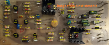
Compare the package size and shape of ZTX 752 (roughly in the centre of rensli's image, above,) with either MPSA06 on the left side. They are different shapes and the MPSA types are as expected - cylindrical with one flat face. The ZTX parts have two flat faces and are smaller. They are E-line package, the MPSA types are TO92.
However, having said that, look at this datasheet - MPSA06 pdf, MPSA06 description, MPSA06 datasheets, MPSA06 view ::: ALLDATASHEET :::
rensli may well be correct, though I've never seen these in E-line.
However, having said that, look at this datasheet - MPSA06 pdf, MPSA06 description, MPSA06 datasheets, MPSA06 view ::: ALLDATASHEET :::
rensli may well be correct, though I've never seen these in E-line.
Last edited:
There is also something odd about the transistor labelling of that image. For example, where is the complementary ZTX652? Not that it matters for this purpose, that board looks like NAP120 to me. The power transistors would have been mounted remotely, on the rear panel, which is fashioned into a crude heatsink for that model only. [Review] Naim NAC12 and NAP 120 - vintage preamp and power amp
Here's another strange, fun fact - Naim licensed the manufacture of at least that NAP120 model in New Zealand. JV wasn't altogether happy about it and I think it was a short-lived venture to satisfy a market that was heavily protected with tariffs. You can check this for authenticity in the interviews published online.
Here's another strange, fun fact - Naim licensed the manufacture of at least that NAP120 model in New Zealand. JV wasn't altogether happy about it and I think it was a short-lived venture to satisfy a market that was heavily protected with tariffs. You can check this for authenticity in the interviews published online.
Thanks Ian, that explain the transistors. Although I can't find any MPSA devices currently sold by Diodes Inc. on Digikey, Mouser etc. Probably Zetex used to make them some time ago under license and put them in their own e-line.
My main interest was to find out how valid the schematic and picture were. Seems to match, considering your observations.
As for the models, I accepted that the Chinese sources call everything either 140 or 250 People who want to find the correct info need to do their research and not take eBay ads as a fact. Not that it really matters for DIY. Most variations between models are merely supply voltages, output devices and regulation. I suspect that at the time even Naim were experimenting with "silent" mods in their production, considering how completely different are their grounding and wiring in the old models.
My main interest was to find out how valid the schematic and picture were. Seems to match, considering your observations.
As for the models, I accepted that the Chinese sources call everything either 140 or 250
People who want to find the correct info need to do their research and not take eBay ads as a fact. Not that it really matters for DIY. Most variations between models are merely supply voltages, output devices and regulation. I suspect that at the time even Naim were experimenting with "silent" mods in their production, considering how completely different are their grounding and wiring in the old models.
Last edited:
Source of picture is "There's 2 version of NAP 140 PSU design? - #4 by james_n - Hi-Fi Corner - Naim Audio - Community"
" the first NAP140s from 1986 used Sanken 2SC2922s. Then in 1990 the NAP140 was upgraded with Naim’s own NA001s."
I removed the link. may be illegal. You can search with google.
" the first NAP140s from 1986 used Sanken 2SC2922s. Then in 1990 the NAP140 was upgraded with Naim’s own NA001s."
I removed the link. may be illegal. You can search with google.
Last edited:
Member
Joined 2009
Paid Member
I quite agree.
I have been dragging the same system in my workshop for over 10 years and it never sounds the same.
If I'm in a bad mood or stuck on a repair or working on a device that annoys me, it sounds more aggressive and tiring whereas if I'm working on a cool device that is well designed and can be even well documented, it is much softer and less tiring.
with just their own ears and a DMM, maybe add a parts checker and you're in the right place - diyAudio!
In other words you need to see the sound to be able to do appropriate designs.
If you see acoustics in 3D space, separate frequencys via "strings" in some environment, we could easly detect which frequencys excite the amplifier.
I think almost all users here dont have necessary equipment to do this alone.
DMM, oscilloscopes, parts meter is not enough. Visualization could be a thing... but who has that machinery ?
Nice, it can be used for sound or radio or anything else where some "space" of frequencys are created.
that's just great
So we need gear and equipment and really fast and accurate stuff before we can conclude anything HIFI related.
Its like this: 369 + 1 = 370 - 0 = 37 = 3 + 7 = 10 - 0 = 1
Refreshing.
that's just great
So we need gear and equipment and really fast and accurate stuff before we can conclude anything HIFI related.
Its like this: 369 + 1 = 370 - 0 = 37 = 3 + 7 = 10 - 0 = 1
Refreshing.
We should definitely try to understand what happens when we alter a circuit from its original state. How a certain product or build sounds initially and after minor alterations, an hour, a week or months may be interesting, even exciting but THD analysis, with or without time included in a 3D display, is about the best way of identifying what really happened to our audio circuit. The question is, should we do anything about it 
Once you create a schematic spice file, check it properly and simulate the electronic design, you could probably do most of the analysis that way, from your desktop. Its time consuming though and your models may not even be appropriately accurate. Direct measurement though, is virtually instant and independent of the actual design or models. There are quite a few inexpensive audio distortion meters now - based on high quality sound cards and sinewave generators. If an AP500 series instrument is beyond your budget, there are plenty of wallet-friendly alternatives.
I haven't given much thought to the time aspect of distortion, no matter how it may be displayed in graphics. The analysis technique is well known though and has been applied to speaker cabinet/crossover design for many years. Software like trueRTA or AUDMES is also available but I think that understanding how it might apply to power amplifier analysis would be something of a challenge for DIYs. Well, for me at least, it is
- Home
- Amplifiers
- Solid State
- NAP-140 Clone Amp Kit on eBay