Eva has some good data there. Things have moved on since 2007 and the latest devices are no slouches and can handle stupid over-currents - like over 130A for a 200W device, and extremely high voltages: 650V+. Great for that Back to the Future guitar strum or driving your arc welder. 


You don't see a lot of IGBTs used in DIYaudio. Nor have I seen any designs using a discrete mosfet driving a bipolar (either darlington or Szilkai). Have you?
Bear in mind that an IGBT does not work exactly like two separate transistors. It is a highly integrated silicon merger with parasitic bits and pieces. More a Brundlefly than a Brundle + fly. And this makes it highly optimized.
Last edited:
Member
Joined 2009
Paid Member
I have no idea whether successful amplifiers were ever made with discrete semis. The fact that IGBTs exist is probably evidence that there were fundamental problems like thermal compensation to deal with and the IGBT was a viable solution for very high current applications - if you needed one....You don't see a lot of IGBTs used in DIYaudio. Nor have I seen any designs using a discrete mosfet driving a bipolar (either darlington or Szilkai). Have you?
Very high currents and very low drive currents. Basically, just what is needed to charge the gate capacitance. I doubt that any power inverter nowadays uses other than IGBT output stage.
There was a French company in the early 90s called Micromega. They were in digital and very techie and had IGBT outputs in their amps. I remember some good press in the Revue du son magazine.
There was a French company in the early 90s called Micromega. They were in digital and very techie and had IGBT outputs in their amps. I remember some good press in the Revue du son magazine.
Member
Joined 2009
Paid Member
With a BJT the Ic is non-linearly related to Vbe but can be linearly related to Ib. So some BJTs can be used for linear current amplification. It requires much more current drive and suffers current droop and secondary breakdown.
With an IGBT the Ic is non-linearly related to Vge and non-linearly related to the integral of Ig, similar to but not the same as a mosfet. Unlike a mosfet they have very low ON resistance and lower parasitic capacitance.
With an IGBT the Ic is non-linearly related to Vge and non-linearly related to the integral of Ig, similar to but not the same as a mosfet. Unlike a mosfet they have very low ON resistance and lower parasitic capacitance.
Last edited:
Member
Joined 2009
Paid Member
With a BJT the Ic ... can be linearly related to Ib.
in your dreams maybe

Member
Joined 2009
Paid Member
Perhaps an air-cored transformer!perhaps the most linear voltage gain stage is a step-up transformer, but it'll need a current amplifier.
And only then between your two knees.
Last edited:
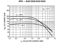
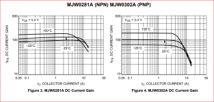
Yes. Perhaps THD junkies should use MJW0302A in single-ended mode.RETs look much better but they still only remain fairly linear up to a few amps DC current, then its back down the slippery slope of falling gain.
These are pretty linear up to 4A or so. One reason, maybe THE reason, you see Krells and such with lots of paralleled output transistors. I suppose if you want to swing 50V across 2 ohms you'll need 25A which means 6+ transistors in parallel. A side-effect is you get to claim a really low output resistance in your marketing (that doesn't matter) and you have to go with low NFB which is another marketing tick.RETs look much better but they still only remain fairly linear up to a few amps DC current, then its back down the slippery slope of falling gain.
Of course, this is not a good idea for a NAP.
Yes, I'd say Krell began in the old way to achieve good sound quality, which means essentially class A and throwing as much power and output semis as will fit in a large box and deliver more than enough power to drive even the worst efficiency speaker types.
Their distinction was a successful stepped bias system and there have been more clever tricks to reduce the class A power dissipation over the years but I'd still label Krell as the V8 engine approach to audio. Dan d'Agostino still maintains the theme with his own brand which is now well established too. If £10-60k is no problem for even a used amp purchase, he's the man. Dan D'Agostino
Naim is surely after the same class of clientele but to their credit, have also supported the rabid fans of the brand who seem to have quite shallow pockets when it comes to high-end audio.
Their distinction was a successful stepped bias system and there have been more clever tricks to reduce the class A power dissipation over the years but I'd still label Krell as the V8 engine approach to audio. Dan d'Agostino still maintains the theme with his own brand which is now well established too. If £10-60k is no problem for even a used amp purchase, he's the man. Dan D'Agostino
Naim is surely after the same class of clientele but to their credit, have also supported the rabid fans of the brand who seem to have quite shallow pockets when it comes to high-end audio
.I do like that simile.I'd still label Krell as the V8 engine approach to audio.
Big, powerful, hot and heavy. But can it play music?
Zero Zone Krell KSA50-MKII clone
Here we go. MJL4281/MJL4302, 3 in parallel per phase. So the transistors can do about 15A peak in fairly linear mode or 225W average sine wave into 2 ohms.
KRELL-KSA50-MKII
I'm not promoting buying this kit.
Here we go. MJL4281/MJL4302, 3 in parallel per phase. So the transistors can do about 15A peak in fairly linear mode or 225W average sine wave into 2 ohms.
KRELL-KSA50-MKII
I'm not promoting buying this kit.
Attachments
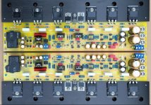
About six months ago, for a test I had in mind for some time, I installed in my NAIM clone two dual voltage stabilized modules (suitably improved by replacing the original electrolytic capacitors with others from Philips/Vishay and Nichicon Muse series), powering the input differential and the VAS stage then independently every single amplifier channel at +/- 30 Vdc and leaving unchanged the linear power supply of the driver stage and the power BJTs.
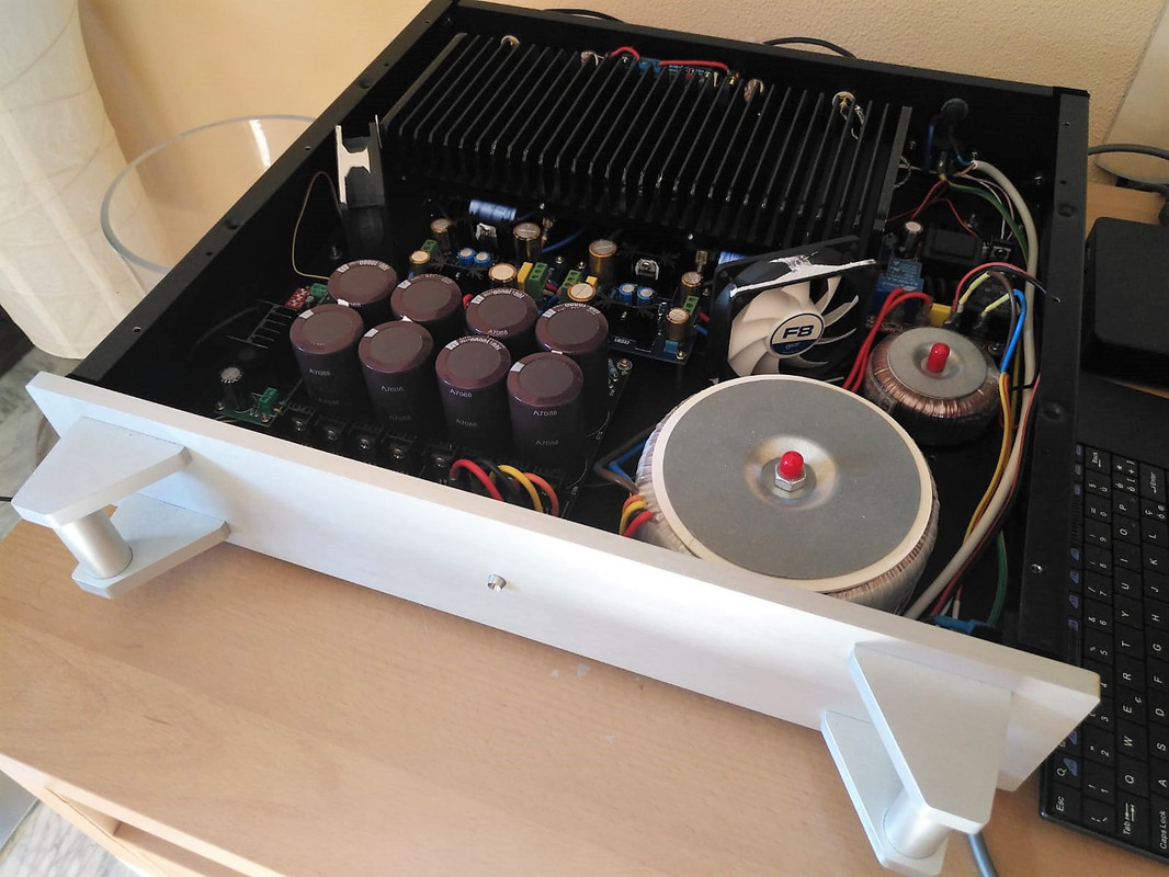
The results from a sonic and musical point of view, against all my initial scepticism, were immediately great and extraordinary, especially in terms of timbre and sound-stage.
Almost another amplifier especially listened to and evaluated with my Sonus Faber speakers, which have particular transparency and neutrality with respect to any change in the audio setup, reveal with extraordinary skill and transparency every change, allowing you to assess any possible limit or improvement of the overall musicality.
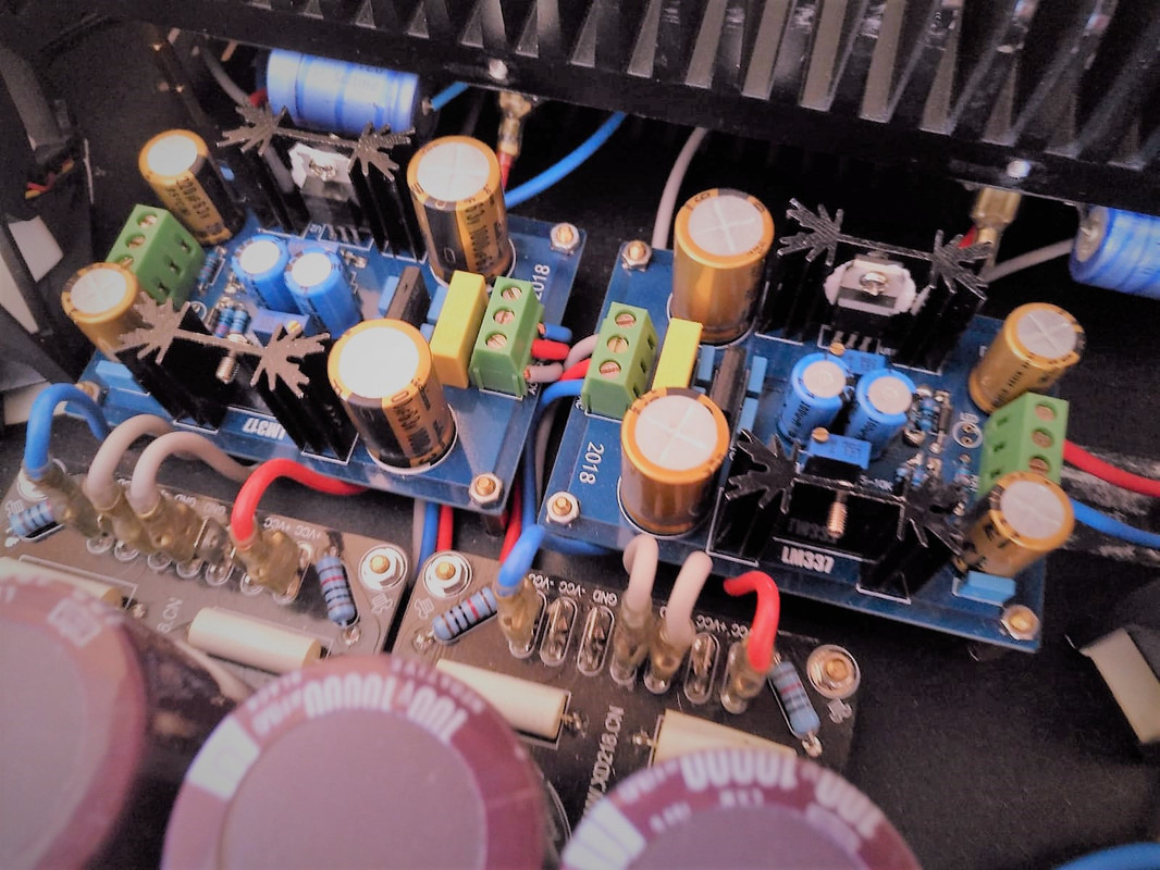
My only perplexity was that when I switched from the linear power supply at +/- 40 Vdc to the dedicated and stabilized power supply of the differential input stage and VAS at +/- 30 Vdc, the DC Off-Set voltage on the output speaker terminals had increased to 62 mV from the previous 15/20 mV.
After a few months, not convincing me much of the situation described, through the trivial variation of the R1 of the stabilization modules (decreased from the classic 220 Ohm to 136 Ohm) I allowed the two stages of stabilized power supply (which were born for a maximum supply voltage of 30/32 Vdc) to easily reach +/- 40 Vdc.
And by magic the output OffSet voltage on the terminals of both channels collapsed to 4/5 mV, or about 60 mV less and therefore almost an order of magnitude less!
Of course, thinking about it for a moment, all normal considering also the fundamental aspects related to the P.S.R.R. of a power supply stage, but I wanted to share this experience for a little reflection on how important can be a modest variation of only 10 Vdc, in the correct and best functioning of a preamplifier electronics, while remaining all the rest.
Needless to say, now I will allow myself a relaxed listening session to evaluate the possible impacts on sound and musicality and I will not deny myself as soon as possible nor an instrumental test with the Spectrum Analyzer to assess the possible changes in terms of Harmonic Distortion and Dynamic Intermodulation Distortion.
Almost another amplifier especially listened to and evaluated with my Sonus Faber speakers, which have particular transparency and neutrality with respect to any change in the audio setup, reveal with extraordinary skill and transparency every change, allowing you to assess any possible limit or improvement of the overall musicality.
My only perplexity was that when I switched from the linear power supply at +/- 40 Vdc to the dedicated and stabilized power supply of the differential input stage and VAS at +/- 30 Vdc, the DC Off-Set voltage on the output speaker terminals had increased to 62 mV from the previous 15/20 mV.
After a few months, not convincing me much of the situation described, through the trivial variation of the R1 of the stabilization modules (decreased from the classic 220 Ohm to 136 Ohm) I allowed the two stages of stabilized power supply (which were born for a maximum supply voltage of 30/32 Vdc) to easily reach +/- 40 Vdc.
And by magic the output OffSet voltage on the terminals of both channels collapsed to 4/5 mV, or about 60 mV less and therefore almost an order of magnitude less!
Of course, thinking about it for a moment, all normal considering also the fundamental aspects related to the P.S.R.R. of a power supply stage, but I wanted to share this experience for a little reflection on how important can be a modest variation of only 10 Vdc, in the correct and best functioning of a preamplifier electronics, while remaining all the rest.
Needless to say, now I will allow myself a relaxed listening session to evaluate the possible impacts on sound and musicality and I will not deny myself as soon as possible nor an instrumental test with the Spectrum Analyzer to assess the possible changes in terms of Harmonic Distortion and Dynamic Intermodulation Distortion.
Last edited:
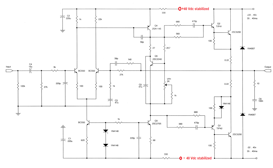
Thats very nice looking assembly work but I can assure you, that with the IPS power separated from the main power rails and with low Cob VAS transistors, it will sound nothing like a Naim clone. However, if this design is to your preference, then enjoy - it will be much closer to mainstream audio sound but possibly better quality if you are adjusting the values of passive components appropriately for the sweet spot of bias etc that is better suited to your substitute transistors.
One suggestion though - lose the craptanium TIP41/42 drivers. MJE243/253 are not really necessary with power transistors like 2SC5200/A1943 but they are more linear with better gain over a wider range of operating conditions such as sounding better over the full volume range which, as I found with many different Naim clones, was quite narrow and best with the volume quite low. Try the MJE types using genuine, not Ebay sourced parts. They are available in most major cities and by post from authorized European distributors. There are other, more suitable audio driver types from On Semi, Toshiba etc too so there are many, good quality options for you.
One suggestion though - lose the craptanium TIP41/42 drivers. MJE243/253 are not really necessary with power transistors like 2SC5200/A1943 but they are more linear with better gain over a wider range of operating conditions such as sounding better over the full volume range which, as I found with many different Naim clones, was quite narrow and best with the volume quite low. Try the MJE types using genuine, not Ebay sourced parts. They are available in most major cities and by post from authorized European distributors. There are other, more suitable audio driver types from On Semi, Toshiba etc too so there are many, good quality options for you.
Last edited:
- Home
- Amplifiers
- Solid State
- NAP-140 Clone Amp Kit on eBay