OK folks. Thanks to your help and advice I have successfully finished my NAP 200 clone. Offset on both channels is around 7–8 mV each, I guess that’s fine then.
The transformer is custom made from Tiger in the UK.
I have added a three way switch to switch the PCB ground from floating directly to the chassis or to the chassis via two diodes in reverse and a 10W resistor. My first impression was that only the floating option gave a tiny little bit of hum and both others no hum at all. But I wasn’t able to listen closer yet, because there is a problem with one of my preamp PCBs (NAC-42 clone). I have already contacted the seller. The left channel works great, the right one is accompanied by hiss and noise. It’s definitely somewhere on the preamp PCB of this channel, I ruled everything else out.
But the NAP 200 works great.
Attachments
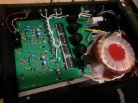
Congratulations. It's quite a big project but a well-built clone sounds superb, I think. You appear to have taken the right steps to mounting the semis but I'm not sure about the thin sheet of aluminium under the PCB. What is this for? Normally, you only need a bar of about 25x4 to 30x5mm that fits within the large PCB slot as a heat spreader between transistors and the case. Of course, a thick aluminium case is essential to use the amplifier at medium to high power, as with all Naim designs.
You will need to add some heatsink grease between bar and case to ensure good thermal contact - where it is most needed. A finishing touch is a plastic cover (anything from the junkbox that fits) over the input transistor pair, as you see in pics of the original. I simply used a discarded cover from an HDMI connector.
You will need to add some heatsink grease between bar and case to ensure good thermal contact - where it is most needed. A finishing touch is a plastic cover (anything from the junkbox that fits) over the input transistor pair, as you see in pics of the original. I simply used a discarded cover from an HDMI connector.
Congratulations. Looks neat and tidy.OK folks. Thanks to your help and advice I have successfully finished my NAP 200 clone.
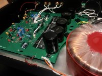
I think I see a shield connection on your transformer too, nice. What made you choose: Tiger?
but I'm not sure about the thin sheet of aluminium under the PCB. What is this for? Normally, you only need a bar of about 25x4 to 30x5mm that fits within the large PCB slot as a heat spreader between transistors and the case.
The transistors are mounted to a 1mm sheet of aluminium which fits the large PCB slot. This sheet of aluminium is screwed to another 1mm sheet of aluminium (under the PCB, directly on the enclosure bottom). I don’t know if this is a useful approach, but this is all I had left. If it’s absolutely necessary I will get a bar of the size and thickness that you mentioned. But the amp will only be used at normal living room/bedroom levels anyway. I also didn’t have any heatsink grease left (I thought I still had some) – is it very important then?
Congratulations. Looks neat and tidy.
I think I see a shield connection on your transformer too, nice. What made you choose: Tiger?
Thanks. I read about Tiger somewhere in this thread, so I thought I’ll give it a try!
It will be better just to use a single bar (least number of junctions) The problem with layered thin sheets is that the case is the heatsink and like with any heatsink, the best conduction, hence the thickest metal, must be right at the point of mounting. Adding thin sheet aluminium layers is likely to hinder heat dissipation as you cannot keep the grease (or more likely an air layer) between the sheets thin enough to consider the metal to be in contact. Black surfaces are best for dissipation too but even heatsink grease is nowhere near as conductive as metal .The transistors are mounted to a 1mm sheet of aluminium which fits the large PCB slot. This sheet of aluminium is screwed to another 1mm sheet of aluminium (under the PCB, directly on the enclosure bottom). I don’t know if this is a useful approach, but this is all I had left. If it’s absolutely necessary I will get a bar of the size and thickness that you mentioned. But the amp will only be used at normal living room/bedroom levels anyway. I also didn’t have any heatsink grease left (I thought I still had some) – is it very important then?
The rigid bar is used because the number of assembly bolts spread over the smaller area will maintain much better contact with the the transistor insulating pads and the bottom plate of the case. If the case is at least 2U rack size and 3mm thick, then it should be sufficient to draw heat from the bottom plate and into the rest of the case to keep average temperatures comfortable at full power.
Otherwise, heat is retained by the output transistors instead of being dissipated. If you decide to use the amplifier only at low output levels, that is your decision but it is better to clone the original design so that it operates as intended and bias control tracks the internal temperature properly, as designed.
")
One thing you can do is put a voltmeter across an emitter resistor to measure the bias current as it changes. Then get your hair dryer out and give the output transistors a vigorous blow dry for several minutes. See how much the bias current changes. Perhaps also heat the bottom of the case. If it starts at, say, 20mA I suppose making sure it doesn't drop below 10mA or exceed 50mA would be sufficient and make sure it doesn't "run away".
Ideally, of course, the bias would not change at all whether very hot or very cold. But at moderate volumes in a normal room temperature the transistors probably won't warm up much.
NOTE: try not to heat your power supply caps. Shield them somehow.
Ideally, of course, the bias would not change at all whether very hot or very cold. But at moderate volumes in a normal room temperature the transistors probably won't warm up much.
NOTE: try not to heat your power supply caps. Shield them somehow.
Last edited:
I have this case here:If the case is at least 2U rack size and 3mm thick, then it should be sufficient to draw heat from the bottom plate and into the rest of the case to keep average temperatures comfortable at full power.
Pesante 02PN 2U 10mm NERO
But the case is only 1mm thick, so this thick rigid bar under the transistors would surely be a good idea. But honestly I got no idea where to get one :-D
And you would suggest to remove the aluminium plate under the PCB completely then?
R core transformer_James transformer-custom toroidal transformer|R core transformer|O core transformer|C core transformer|EI transformer
This is a description of R core. This one “has greater explosive power than toroidal transformer”.
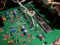
The core is continuously wound steel ribbon that must be pre tapered in width to create an approximately round cross-section. No air gaps. There is a “gnd” connection that I assume is for the outer copper shield banding.
But how do they get the bobbins on???
The bobbins come in two halfs and are snapped together, the bobbins are then spun to wind the copper wire onto the transformers.
Im using Shilchar Technologies (India) R-Cores with my HackerNaps (Naim clone/hot-rodded)
Very quiet at powerup (500VA 35-0-35v)
I did enquire with James a number of years ago about the O-core transformers but went with R-Core in the end
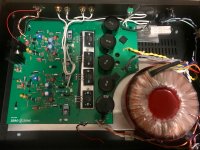
OK folks. Thanks to your help and advice I have successfully finished my NAP 200 clone. Offset on both channels is around 7–8 mV each, I guess that’s fine then.
The transformer is custom made from Tiger in the UK.
I have added a three way switch to switch the PCB ground from floating directly to the chassis or to the chassis via two diodes in reverse and a 10W resistor. My first impression was that only the floating option gave a tiny little bit of hum and both others no hum at all. But I wasn’t able to listen closer yet, because there is a problem with one of my preamp PCBs (NAC-42 clone). I have already contacted the seller. The left channel works great, the right one is accompanied by hiss and noise. It’s definitely somewhere on the preamp PCB of this channel, I ruled everything else out.
But the NAP 200 works great.
Are your 0v connections the centre tap of your transformer windings?
Member
Joined 2009
Paid Member
One thing you can do is put a voltmeter across an emitter resistor to measure the bias current as it changes. Then get your hair dryer out and give the output transistors a vigorous blow dry for several minutes. See how much the bias current changes. Perhaps also heat the bottom of the case. If it starts at, say, 20mA I suppose making sure it doesn't drop below 10mA or exceed 50mA would be sufficient and make sure it doesn't "run away".
Ideally, of course, the bias would not change at all whether very hot or very cold. But at moderate volumes in a normal room temperature the transistors probably won't warm up much.
NOTE: try not to heat your power supply caps. Shield them somehow.
The NAP circuit has several elements that are temperature sensitive, I found the VAS current source has to be carefully constructed for example.
Yes, they are. The centre tap transformer wires are connected to 0V points on the PCB. The transformer also has a shield connection which is connected to chassis ground.Are your 0v connections the centre tap of your transformer windings?
I see. As a heatsink, a 1mm case thickness, even with that spreader, just isn't enough for an amplifier of more than about 30W/4R. You would still need to use a much wider bar or plate of 3mm aluminium to be effective and nobody needs to have a hot spot under that nice PCB.I have this case here:
Pesante 02PN 2U 10mm NERO...But the case is only 1mm thick, so this thick rigid bar under the transistors would surely be a good idea. But honestly I got no idea where to get one :-D
And you would suggest to remove the aluminium plate under the PCB completely then?
Exposure amplifiers (at least the 2000 series I am familiar with) also have 1mm aluminium cases as heatsinks. Their heatsink is formed from thicker plate, located under the small PCB and about the same size. The heat is not well dissipated though and it is quite some time before heat spreads by internal air convection. A hot area under the PCB develops and personally, I think that plan may be cheap but its not good. For DIY, where our engineering is by experience or guesswork, it is difficult to recommend something that will depend heavily on cautious use and probably need some repairs anyway.
One solution could be to remove most of the bottom sheet and replace with original spec. 3mm plate and bar. Then overlap and attach the edges with multiple fasteners along the seams. However, that isn't easy to do at a standard suitable for heat transfer, even for an experienced trades person. Some constructors haven't fitted the bar at all to their 3-4 mm cases, as you see in assembly pics. This may even be OK for low power but it's a waste of amplifier and power supply in reality.
FWIW, I bought my case from China, like most of the guys here. At least the material is adequate in 3 & 4mm thickness panels and the freight inclusive price was affordable
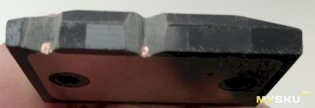
Structural aluminium bar and other extrusions are obtainable from specialist building material suppliers. These guys supply standard lengths of materials for new commercial building construction, window construction, shutters, handrails etc. Some larger hardware suppliers and aluminium specialists also sell off-cut pieces or hobbyist lengths in this country at least, since you don't need much.My article on transistors - 2SC2922- Покупка Sanken 2SC2922P NPN, который по факту прибытия оказался 2SC2922Y: datasheet, параметры и характеристики транзистора Санкен (Russian)and about the quality of the Sanken transistors?
Resume: original 2SC2922
1. Weight original 2SC2922 18.4-19 grammes
2. Not magnetic terminals
3. Thick copper base
Originals:
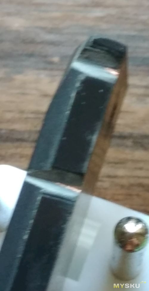
Fake:
Thanks. OK, how does this sound, this is something that I could do quite easily: I remove the bottom plate and the thin aluminium bar. I get a 4mm thick aluminium bar (25mm x 180mm) that is placed under the transistors. And I get two 10mm thick aluminium bars (15mm x 80mm each) to hold down and press the transistors to the other bar. These two shorter bars are attached to the bar under the transistors by one M4 screw each. I could use the same two screws to fix this bar to the chassis bottom.One solution could be to remove most of the bottom sheet and replace with original spec. 3mm plate and bar. Then overlap and attach the edges with multiple fasteners along the seams. However, that isn't easy to do at a standard suitable for heat transfer, even for an experienced trades person. Some constructors haven't fitted the bar at all to their 3-4 mm cases, as you see in assembly pics. This may even be OK for low power but it's a waste of amplifier and power supply in reality.
Would this not be sufficient at rather low levels?
Attachments
I am building af NAP200 Clone
Lets start with some facts:
Chassis: NAIM style Full Aluminum preamp Chassis / Power Amplifier Enclosure 430*90*358mm
PCB Nap200 ZeroZone
Trafos, two dfferent see attached pictures (building two amps).
http://damkierhansen.dk/napclone/IMG_20181023_205855.jpg
Algar_Emi has done a great job (#2174) NAP-140 Clone Amp Kit on Ebaymaking the bom.
Thoug I could not match all component, you can see my BOM (2 channels): http://damkierhansen.dk/napclone/Nap200 Partlist.xlsx
Do you guys have any comments to that? It supprised my that total cost is approx 320 USD.
I cant see which heatsink/ housing (what ever it is called) to TR9 and TR10! Any surgestions?
Regarding the mounting the four Sancen 2SC2922, I am quite unsure.
But if I mount them on the backplate of the chasis, and on top have a "10mm alu heat spreader" bar which also has connection to the backplate! Does that sound correct?
Looking forward to your comments.
/Thomas
Lets start with some facts:
Chassis: NAIM style Full Aluminum preamp Chassis / Power Amplifier Enclosure 430*90*358mm
PCB Nap200 ZeroZone
Trafos, two dfferent see attached pictures (building two amps).
An externally hosted image should be here but it was not working when we last tested it.
http://damkierhansen.dk/napclone/IMG_20181023_205855.jpg
Algar_Emi has done a great job (#2174) NAP-140 Clone Amp Kit on Ebaymaking the bom.
Thoug I could not match all component, you can see my BOM (2 channels): http://damkierhansen.dk/napclone/Nap200 Partlist.xlsx
Do you guys have any comments to that? It supprised my that total cost is approx 320 USD.
I cant see which heatsink/ housing (what ever it is called) to TR9 and TR10! Any surgestions?
Regarding the mounting the four Sancen 2SC2922, I am quite unsure.
But if I mount them on the backplate of the chasis, and on top have a "10mm alu heat spreader" bar which also has connection to the backplate! Does that sound correct?
Looking forward to your comments.
/Thomas
Re; #3335 - That seems like a good plan but as said, joining the two sheet materials with reliably conductive, flat and tidy seams may not be easy at all.
Re: #3336 Hi Thomas 74 - a wise choice for a clone but as you find, buying components separately is very expensive. I assume you refer to heatsinks for MJE243, 253 driver transistors. These are common, standard PCB mount types that accept up to TO220 package transistors. Any that fit the space comfortably when through-bolted to the PCB will be OK. The pic is only indicative of the type - same as fitted to most older NAP models and clones you see all over the clone kit websites.
but as said, joining the two sheet materials with reliably conductive, flat and tidy seams may not be easy at all.Re: #3336 Hi Thomas 74 - a wise choice for a clone but as you find, buying components separately is very expensive. I assume you refer to heatsinks for MJE243, 253 driver transistors. These are common, standard PCB mount types that accept up to TO220 package transistors. Any that fit the space comfortably when through-bolted to the PCB will be OK. The pic is only indicative of the type - same as fitted to most older NAP models and clones you see all over the clone kit websites.
Attachments
![F7124190-01[1].jpg](/community/data/attachments/639/639117-b40518539163b5d367f9c22af9d1757d.jpg)
You can get an idea from the images posted earlier and with images at kitsellers' sites but the bar used to clamp the power transistors is a Naim mounting technique, seldom used by other manufacturers. Most clone kits show the transistors simply bolted down with 2 x 3mm machine bolts, washers and nuts and this technique is more universal with audio manufacturers. If you use a clamp bar, be careful to ensure it has plenty of depth and thickness so that there is sufficient rigidity to prevent any buckling under load and subsequent failure of your (now) obsolete transistors - The force required to squish the thermal pads into ideal contact is significant.I am building af NAP200 Clone.....Regarding the mounting the four Sancen 2SC2922, I am quite unsure.
But if I mount them on the backplate of the chasis, and on top have a "10mm alu heat spreader" bar which also has connection to the backplate! Does that sound correct?..../Thomas
Note also with the bar clamp, the bottom plate will bow or bend slightly under the force. The heat spreader bar between the chassis bottom plate and transistors must be rigid enough to prevent this bowing, otherwise thermal transfer over the whole transistor backplate area will be lost. If you use this method, do it right or not at all.
Last edited:
Thanks for the answer which helped a lot Ian.Re; #3335 - That seems like a good plan
Re: #3336 Hi Thomas 74 - a wise choice for a clone but as you find, buying components separately is very expensive. I assume you refer to heatsinks for MJE243, 253 driver transistors. These are common, standard PCB mount types that accept up to TO220 package transistors. Any that fit the space comfortably when through-bolted to the PCB will be OK. The pic is only indicative of the type - same as fitted to most older NAP models and clones you see all over the clone kit websites.
Thanks alot for describing the mounting
Ian thanks alot.
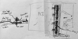
I havent succeeded in finding a good picture, so as my teacher always said "make a model Thomas"!
Below I have tried to illustrate how I understand your description.
I the hole in the PCB I place a 10mm thick aluplate, on that the four Sanken, and on the top a clamp (see fig 1)
You mentioned that I have to bolt it quite hard to secure thermal connection! In figure 2 i have ilustrated that the aluplate could be fastened to the bottom plate of the chassis with some extra bolts. The thought is that the force towards the bottom of the chassis will be spread. Thereby less risk of bowing!
I hope that I have understood you correct, and my figures helps this clarification.
Best regards,
Thomas
You can get an idea from the images posted earlier and with images at kitsellers' sites but the bar used to clamp the power transistors is a Naim mounting technique, seldom used by other manufacturers. Most clone kits show the transistors simply bolted down with 2 x 3mm machine bolts, washers and nuts and this technique is more universal with audio manufacturers. If you use a clamp bar, be careful to ensure it has plenty of depth and thickness so that there is sufficient rigidity to prevent any buckling under load and subsequent failure of your (now) obsolete transistors - The force required to squish the thermal pads into ideal contact is significant.
Note also with the bar clamp, the bottom plate will bow or bend slightly under the force. The heat spreader bar between the chassis bottom plate and transistors must be rigid enough to prevent this bowing, otherwise thermal transfer over the whole transistor backplate area will be lost. If you use this method, do it right or not at all.
Ian thanks alot.
I havent succeeded in finding a good picture, so as my teacher always said "make a model Thomas"!
Below I have tried to illustrate how I understand your description.
I the hole in the PCB I place a 10mm thick aluplate, on that the four Sanken, and on the top a clamp (see fig 1)
You mentioned that I have to bolt it quite hard to secure thermal connection! In figure 2 i have ilustrated that the aluplate could be fastened to the bottom plate of the chassis with some extra bolts. The thought is that the force towards the bottom of the chassis will be spread. Thereby less risk of bowing!
I hope that I have understood you correct, and my figures helps this clarification.
Best regards,
Thomas
An externally hosted image should be here but it was not working when we last tested it.
Last edited:
- Home
- Amplifiers
- Solid State
- NAP-140 Clone Amp Kit on eBay