I always said the parts delivered in Chinese kits are cheap meaning low qualify. I just don't trust them. Good for you managed to find the problem.
Sent from my Nexus 5 using Tapatalk
Yes, I was originally suspicious of this kit as well to be honest as I've had bad experiences in the past. However it was good to see that the output transistors appear to be genuine, at least when compared with known-genuine parts and other known fakes.
Of all the parts that could have gone wrong though it had to be one of the simplest parts, and is more than likely a mechanical problem.
The best part of this kit though is the high quality PCB. It's worth the total paid for the kit on its own. The other parts can be swapped out for parts from trusted suppliers as and when.
Does this affect your opinion as to whether a pair of matched BC550C would be a suitable replacement for the MPSA06?
Avondale Audio have used BC546 in the LTP of their NCC200.
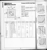
I have a transistor handbook from National where they have classified their devices numerically according to the process by which they are made. The BC237-239 and the BC546-550 are within a group identified as 04.
My book is old and National were not making 546's then, however On-Semi and Fairchild are doing the BC546-550 range suggesting 546 was a later addition to the family.
It could be that Naim have tested a stack of BC239C's for voltage breakdown as well as matching pairs for gain - that could be laborious and costly which you would be paying for if you bought from Naim.
I suggest you measure the voltage between ground and the following points
positive supply rail, TR1 collector, TR1 emitter and deduce the voltage between TR1 collector and emitter.
If the answer is within the collector to emitter voltage rating for BC550C and the upper tolerance of your power supplier is OK you could consider this.
The BC546 would increase the margin. But you might have difficulty in finding C suffix types - I have bought B suffix ones and used them in an amplifier with 35 volt supply rails - the Vce across the LTP input TR is close to the supply rail value.
I built that 25 years ago and it is still going strong. I will not be replacing the BC546B's with BC239C's.
For matching you might need to buy a few more BC546B's than BC550C's.
Last edited:
Right, problem solved.
The cause? A faulty bias trimmer in one of the channels!
I identified there was a fault by finding that the voltage across the 2 x 0R22 resistors was ~2.5mV. Knowing that the voltage here was set to ~13mV during initial setup I probed further.
When in-circuit the resistance across the 1K resistor connected across the trimmer was always 1K regardless of the trimmer setting. However when I pressed a little harder whilst adjusting the trimmer the resistance changed erratically. Could have been a poor solder joint so I removed it to test it.
Out-of circuit the trimmer tested fine. Put it back in, same erratic result.
Replaced it (and the one in the other channel just in case) and now all is well.
Thanks for all the suggestions, it's been a learning experience.")
What type of trimpot did you replace and what with? carbon, cermet, or multi-turn?
What type of trimpot did you replace and what with? carbon, cermet, or multi-turn?
Just carbon, like for like. It's all I had in stock.
I had a look at the trimpots on arrival of my kit (similar type pictured) and have to agree that these don't seem appropriate quality. I planned to replace them with single-turn cermets from a US source in any case. Yes, there are fake Bourns multi and single turn cermets out there! How do you know they are fakes? By the attractive low price and the number of Chinese sellers of the same items .
Flat style cermets with a pin layout of 5.08 x 5.08 mm aren't common but Bourns 3386 type Y or F pattern seem right. You can joggle the wiper pin of other types, as you see with many multi-turn retrofits but nothing is as secure and reliable as correct fitting parts.

. Flat style cermets with a pin layout of 5.08 x 5.08 mm aren't common but Bourns 3386 type Y or F pattern seem right. You can joggle the wiper pin of other types, as you see with many multi-turn retrofits but nothing is as secure and reliable as correct fitting parts.
Last edited:
Just carbon, like for like. It's all I had in stock.
Has the fix done anything about your switch on fuse blowing problem?
Has the fix done anything about your switch on fuse blowing problem?
I've not tried powering up without the series bulb + bypass switch yet as I've only got one fuse left. More are on order.
Last edited:
I mentioned the transformer rotation as an Exposure amp foxed myself and it's PHD in electrical engineering friend ( His BSc was in electronics, his amplifier he couldn't fix). I went through everything and then found I could null it completely if the transformer was vertical. This was out of the question so the least worse position chosen. There were two options. Statistical lowest and ears lowest. The ears lowest was a nearly single higher value lower frequency scope readout. With the spare windings it might just be more fussy.
What fooled us is Exposure had set the position with a two bolt fixing. This was obviously right when prototype, but was not checked in production. New bolt holes made to refix. As luck would have it just possible to get a result.
Exposure had a twin regulator design ( 4 in total ). This had two goes at curing the problem. This to my mind is why Exposure never beat Naim in the market place.
The fix was well worth doing. The sound was deeper and had more clarity. What is silly is I took two weeks to find it. I just trusted what they had done.
Whilst it is unlikely something so simple it is worth checking. You don't need a scope. Colin Wonfor pointed this out to me years ago. If fitting an MC stage to his amp he suggested nulling the transformer. Thanks Colin.
Hi Nigel,
You are most welcome, I am very happy to share my knowledge and experience and big mistakes he he and there as been a few large bangs in my past.
Also note transformer maker like Airlink will random wind transformers and this also reduce fixed magnetic fields emanating from the wiring input to the transformer.
As to SMPSU I hate them in audio, unless they are full bridge resonant types as this reduces the odd harmonic generated by the clock or switching frequencies, Flyback are cheap and nasty and in common use avoid if possible, In Class D type amps trying syncing the Class D clock with the SMPSU this also reduces harmonics.
Have fun as always but avoid fingers on the HV rails it does bite.
Best Col
Avondale Audio have used BC546 in the LTP of their NCC200.
I have a transistor handbook from National where they have classified their devices numerically according to the process by which they are made. The BC237-239 and the BC546-550 are within a group identified as 04.
My book is old and National were not making 546's then, however On-Semi and Fairchild are doing the BC546-550 range suggesting 546 was a later addition to the family.
It could be that Naim have tested a stack of BC239C's for voltage breakdown as well as matching pairs for gain - that could be laborious and costly which you would be paying for if you bought from Naim.
I suggest you measure the voltage between ground and the following points
positive supply rail, TR1 collector, TR1 emitter and deduce the voltage between TR1 collector and emitter.
If the answer is within the collector to emitter voltage rating for BC550C and the upper tolerance of your power supplier is OK you could consider this.
The BC546 would increase the margin. But you might have difficulty in finding C suffix types - I have bought B suffix ones and used them in an amplifier with 35 volt supply rails - the Vce across the LTP input TR is close to the supply rail value.
I built that 25 years ago and it is still going strong. I will not be replacing the BC546B's with BC239C's.
For matching you might need to buy a few more BC546B's than BC550C's.
I also found the ZTX range of transistors OK.
Hi Colin? I understand Tony not with us now, lovely man? That photo isn't the you I remember? Hey Ho.
The Colin I knew told me of an amplifer made between two current sources with no obvious active device ( What about the CCS's then ? Fooled the experts at the time). Poor PSRR the downside.
The Inca as a Kit amp would be interesting. I love the Hitachi inspired amps.
Airlink were with ILP of Canterbury I think? Mr Hill of Carnhill made mine in Oxford.
It could be that Naim have tested a stack of BC239C's for voltage breakdown as well as matching pairs for gain - that could be laborious and costly which you would be paying for if you bought from Naim.
Which raises the question - why would they bother?
Is there a particular property or behaviour of the BC239C that they favour that makes this worthwhile?
Colin. It's interesting you talk about syc between SMPS and class D. I suggested it somewhere I do a bit of work for. It made them run for the hills and fit conventional. The Hypex makes this mistake. If the 100 kHz is has in it's PSU ( as best as I know ) was at least a subharmonic of the circa 400 kHz of the Hypex self oscillation it would help ( use a ripple counter type device to easilly get it ). As you say to have 340V to touch is bad engineering. It is typical. Hypex say allow 6 mm spacing. That's not very good. Even the most awful computer PSU is in a Faraday cage. When valves I will allow it as it is exspected.
I still have that +/- 43V DC 600 VA Hypex. It is very useful for seeing what an amp like this will do. It would force me to go 500VA to equal it's bass punch. The Hypex PSU sounds bright. Silver plated is how to describe it. Not nasty it should be said. It looks as if 5 years would be it's life. A convetional PSU with modern caps should out last me and even 20 year olds. Fit 105 C caps to your kits. That should give them extra life. Often they are better grade into the bargain. Use the higher voltage types if they fit. The Tan Theta usually is better due to working at high voltage ( the foils to resist voltage are more Audiophile in type, even when polyester the 100 V types are better than the 63 V ). Typical might be 0.15 50V 0.1 63V.
I still have that +/- 43V DC 600 VA Hypex. It is very useful for seeing what an amp like this will do. It would force me to go 500VA to equal it's bass punch. The Hypex PSU sounds bright. Silver plated is how to describe it. Not nasty it should be said. It looks as if 5 years would be it's life. A convetional PSU with modern caps should out last me and even 20 year olds. Fit 105 C caps to your kits. That should give them extra life. Often they are better grade into the bargain. Use the higher voltage types if they fit. The Tan Theta usually is better due to working at high voltage ( the foils to resist voltage are more Audiophile in type, even when polyester the 100 V types are better than the 63 V ). Typical might be 0.15 50V 0.1 63V.
Which raises the question - why would they bother?
Is there a particular property or behaviour of the BC239C that they favour that makes this worthwhile?
Julian did do that. He said he couldn't trust suppliers. He even sold the unusable devices that still met spec back to the supplier. Julian had the parts in pair match right through the amp, that is resistors and anything he could think of. He was able to use cheaper parts as a result. Naim amps were second to none for reliability. This was the reason. Julian was certain that any amp that left Naim Audio was exactly as prototype. If a resistor was at it's 5% limit it wasn't rejected, it % matched to it's circuit partner. That was a very quick thing to do. Test and put in a bin for the ladies at Naim. It seems daft today when 1% is cheap. Julian wasn't doing it for that reason. It was to test everything at every stage. That was almost a bit of Autism is my guess. It paid off. Some romantically would think Exposure better. Get a screwdriver out and see the difference. Julian was a mechanical engineer. Although nothing is outrageous in terms of metal used Naim just looks a propper piece of engineering.
Most of what Naim and Linn did was the best of what people did before them. Linn was Thorens + Garrard. The aging of platters was a Garrard thing. They went out in the rain and snow for 7 months.
Leak tested everything. Rank stopped that and killed the company in double quick time. To me Naim filled the Leak vacuum.
BC 239C is not obviously worse than any other device. It seems some can be very high gain. I have a hunch that would have been selected for ( mostly unimportant to my mind ). Noise is OK, but not special. FT is great. Ccb is excellent. Cbe is excellent also. BC550C might just better it on all counts. I have a hunch BC337-40 will better it on noise. I doubt if 5 to 12 pF Ccb matters much. Most amps I know of could use any transistor as the input device. As said the seemingly ultra unsuitable MPSA42/92 do work very well. My feeeling is BC239C could be had at 1 penny each and offer selected devices which could not be beaten. That's all. Perhaps Naim used 5% of the ones they bought?
I think Naim told me the transistors were bolted into a jig to noise test them. That would be a Naim module and a scope at a guess ( ears and a sensetive speaker will do )? The LM317 also. LM317 I was told were the most rejected devices. Lucky people who bought the rejects as any bad ones went in the bin. If you can get a supplier to play ball like this it makes for a very cheap supply. I doubt many were truely defective? As said a bit of Autism. In Audio it is very easy to believe your own BS. In this case no harm done, in a Jet engine it is a must have.
http://www.farnell.com/datasheets/112795.pdf
BC237 seems to be a voltage selected BC239 as no other spec is different. Interestingly they give a graph of the base spreading resistance ( Rbb- ). It is about 160R at 1mA. Lower noise devices about 30R. BC550C seems to be as good on everything with lower noise. It also is a low capacitance device.
BC237 seems to be a voltage selected BC239 as no other spec is different. Interestingly they give a graph of the base spreading resistance ( Rbb- ). It is about 160R at 1mA. Lower noise devices about 30R. BC550C seems to be as good on everything with lower noise. It also is a low capacitance device.
http://www.farnell.com/datasheets/112795.pdf
BC237 seems to be a voltage selected BC239 as no other spec is different. Interestingly they give a graph of the base spreading resistance ( Rbb- ). It is about 160R at 1mA. Lower noise devices about 30R. BC550C seems to be as good on everything with lower noise. It also is a low capacitance device.
I've got my BC550Cs now and found two matching pairs, beta 550 for one pair and 560 for the other +/- 1, so as well matched as I could have hoped for, in that regard at least, out of a collection of 20 devices.
It might be a few days now before I get chance to measure the VCE across the existing MPSA06s and then hopefully substitute them. Work commitments unfortunately.
With reference to the schematic kindly drawn by Algar_emi (post #1825):
http://www.diyaudio.com/forums/solid-state/112453-nap-140-clone-amp-kit-ebay-183.html#post4567226
...TR6 (ZTX653) is running very hot in both channels. Not sure whether this is normal or not.
Last edited:
Low noise in paralell transistors is due to statistical noise cancellation ( it is said ). That is the random events in the white noise just like real statisitics can cancel. I wonder if purely the base spreading resistance is reason enough? Put 5 transistors together as Naim MC stage did and if 100R they become 20R. It's near enough exactly what you get. 3 is good and 5 devices is as good as it gets without going silly. I suspect it would relate to measurement very closely. It might be close enough to reality to be usuable as a rule of thumb. I wouldn't mind betting it is 100% reliable as one.
Right, problem solved.
The cause? A faulty bias trimmer in one of the channels!
I identified there was a fault by finding that the voltage across the 2 x 0R22 resistors was ~2.5mV. Knowing that the voltage here was set to ~13mV during initial setup I probed further.
When in-circuit the resistance across the 1K resistor connected across the trimmer was always 1K regardless of the trimmer setting. However when I pressed a little harder whilst adjusting the trimmer the resistance changed erratically. Could have been a poor solder joint so I removed it to test it.
Out-of circuit the trimmer tested fine. Put it back in, same erratic result.
Replaced it (and the one in the other channel just in case) and now all is well.
Thanks for all the suggestions, it's been a learning experience.
I am surprised this has solved your hum problem. I would not expect a lack of quiescent current (in one channel) to cause 50Hz hum (in both channels).
Which raises the question - why would they bother?
Is there a particular property or behaviour of the BC239C that they favour that makes this worthwhile?
The attachment shows the pattern used for 04 transistors showing the dimensions and geometry is the same for all types under this classification.
The area where variation is possible is in doping of the regions of the pattern to permit higher Vce for instance or low noise=BC239C and BC550C.
Root 2 has found ZTX transistors OK - medium power transistors have a larger chip and base emitter junction area. The endowment is low base emitter impedance and a reduction in NF.
Albeit the ZTX753 is a PNP type a Spice file gives a value of 1.
I have no opinion about MPSA06 in this regard but the Hfe is 50 so there is a question how much larger is the base emitter junction in relation to that of the BC transistors. It could be for noise considerations as well as operating voltage.
I pointed out in my post that the matching gap narrows in terms of Emitter Current Gain as Hfe increases and suggested a larger quantity of test subjects be purchased.
Nigel has suggested Naim had a fair share of rejects which is a question of economics more than the flavour of the recipe used to produce the device.
Attachments
- Home
- Amplifiers
- Solid State
- NAP-140 Clone Amp Kit on eBay