It pains me to do this, but I need more input ( on the board layout) than I'm currently getting on the original thread where this amp was developed:
http://www.diyaudio.com/forums/showthread.php?s=&threadid=108860&perpage=25&pagenumber=13
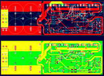
This is a low distortion, high power (150+watts @ 8 ohms) design. It's a two sided board, with a poured ground plane on the top. It uses 56 volt rails and has on board power supply (bridge, smoothing caps, rail fuses).
Please take the time to check it out and give me suggestions as to how to improve it.
In the pic below: board on the bottom has the ground plane added. Board size is about 3" x 8" (7.5cm x 20cm).
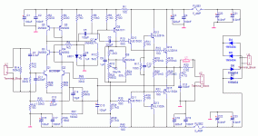
I will post the schematic next.
Attachments
h_a said:I have not compared the layout to the schematic, however your general layout looks very nice!
All the best, Hannes
Thanks Hannes,
Well, once again, a huge response.
I'll go with it.
Re: Couldn't help pointing out...
Hi Gajanan,
I tried to make the rails as short and wide as possible, while still leaving space for the output devices to mount to the heatsink. I thought that I'd struck a pretty good compromise since in many designs, these leads are wire from PS board to amp board - wires that may be twice that length and possibly too thin.
gmphadte said:The negative supply cap is very far from the o/p transistor. These high current connections should be the shortest.
Gajanan Phadte
Hi Gajanan,
I tried to make the rails as short and wide as possible, while still leaving space for the output devices to mount to the heatsink. I thought that I'd struck a pretty good compromise since in many designs, these leads are wire from PS board to amp board - wires that may be twice that length and possibly too thin.
I think u should forget the one-side-power-connector approach and shift the caps to either side of the board. e.g. as in MikeB's Symasym
Remember, longer, high current tracks will induce signal in the nearby tracks, more inductance...
Anyhow, you are the best judge.
Gajanan Phadte
Remember, longer, high current tracks will induce signal in the nearby tracks, more inductance...
Anyhow, you are the best judge.
Gajanan Phadte
Personally I would keep the main supply capacitors + rectifier off board. Then I would have the power connections from the supply to the amp as near to the output transistors as possible, with some local decoupling.
If you really want to do it this way, then the one layout I have seen that impressed me in this regard was SuzyJ's power amp. She has the layout available on her site:
http://www.littlefishbicycles.com/poweramp/index.html
If you really want to do it this way, then the one layout I have seen that impressed me in this regard was SuzyJ's power amp. She has the layout available on her site:
http://www.littlefishbicycles.com/poweramp/index.html
gmphadte said:I think u should forget the one-side-power-connector approach and shift the caps to either side of the board. e.g. as in MikeB's Symasym
Remember, longer, high current tracks will induce signal in the nearby tracks, more inductance...
Anyhow, you are the best judge.
Gajanan Phadte
No, I'm not the best judge, just a raw amateur.
I thought about putting the supply caps on either side of the board, but decided against that, as then there would be long leads from the bridge.
I was thinking the ideal place for the power supply was on the other side of the heatsink., but this would severely cripple chassis layout, convection and increase board size dramatically.It would be just as well to use a separate PS board as to do that.
Again, I think I have struck a good compromise here. The lead from the negative rail is a bit longer than the positive rail, but I don't see that as a problem.
Leolabs said:Are the electrolytic caps close to the heatsink???
Hi Leolabs,
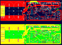
The decoupling caps are not close to the heatsink as I've highlighted in the attached pic (green arrows).
The power supply caps are closer, the top two anyway. I have some ideas on cooling this amp that might not involve a heatsink though.
Attachments
- Status
- This old topic is closed. If you want to reopen this topic, contact a moderator using the "Report Post" button.
- Home
- Amplifiers
- Solid State
- Look over this amp board layout please.


