Hi
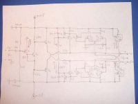
For the new amp circuit I’m making, I need a balanced input. Therefore, I have need for a phase splitting circuit. Transformers are out, that would be too easy. I don’t have any good quality (expensive) audio transformers anyway. The circuit needs to take a single phase input, and output a balanced signal. There needs to be 0V DC on each output as well. I’m sure there are many ways to achieve this, but I thought up this circuit from the parts I have lying around and it appears to work. Since I have learned so much about audio from this forum, and since it seems to be working, I thought I’d share it with you guys. So a brief description…
Q2, Q3, Q9, Q10, Q11 = http://www.fairchildsemi.com/ds/KS/KST5089.pdf
Q4, Q6, Q7, Q8 = http://www.fairchildsemi.com/ds/KS/KST5087.pdf
Q12, Q13, Q18, Q19 = http://www.fairchildsemi.com/ds/MM/MMBFJ201.pdf
Q5, Q14, Q15, Q16, Q17 = http://www.fairchildsemi.com/ds/MM/MMBF5460.pdf
Q1 = http://www.fairchildsemi.com/ds/KS/KSK595H.pdf
Q12 & Q13 are matched for Vgs @ Id = 100uA. Q14 & Q15 are matched for the same conditions. Q17 is actually a 5462, and Q18 is: http://www.fairchildsemi.com/ds/MM/MMBF4091.pdf. These have a larger output admittance (gos) as is appropriate for a cascade CCS. Each J-fet source bias is 200uA for the differential tail currents. The AC is filtered out leaving a DC comparison with GND, that adjusts the two transistor CCS’s maintaining 0V DC output. It appears from my experimenting that everything is good up until about 650 KHz. At this frequency, there begins to be some phase shift and the two signals are off a few degrees from each other, but that is pretty fast for audio, and I think it will fit my application.
I have not seen or ever heard of anyone in the forum using this input transistor. Even though it seems a bit tiny in Id, the transient characteristics really are good and I will swear by the sound of this device, if it is used properly. I also use them as input differentials for the power amp circuit as well.
Each output has no voltage gain from the input. This circuit needs to drive 2.2K at 0.6V peak, but the output impedance is a little high. The signal looks good into 22-30K, so maybe I can follow each channel with a unity gain op-amp. Has anyone else used a circuit similar to this one? Thoughts?
Thanx
For the new amp circuit I’m making, I need a balanced input. Therefore, I have need for a phase splitting circuit. Transformers are out, that would be too easy.
I don’t have any good quality (expensive) audio transformers anyway. The circuit needs to take a single phase input, and output a balanced signal. There needs to be 0V DC on each output as well. I’m sure there are many ways to achieve this, but I thought up this circuit from the parts I have lying around and it appears to work. Since I have learned so much about audio from this forum, and since it seems to be working, I thought I’d share it with you guys. So a brief description…Q2, Q3, Q9, Q10, Q11 = http://www.fairchildsemi.com/ds/KS/KST5089.pdf
Q4, Q6, Q7, Q8 = http://www.fairchildsemi.com/ds/KS/KST5087.pdf
Q12, Q13, Q18, Q19 = http://www.fairchildsemi.com/ds/MM/MMBFJ201.pdf
Q5, Q14, Q15, Q16, Q17 = http://www.fairchildsemi.com/ds/MM/MMBF5460.pdf
Q1 = http://www.fairchildsemi.com/ds/KS/KSK595H.pdf
Q12 & Q13 are matched for Vgs @ Id = 100uA. Q14 & Q15 are matched for the same conditions. Q17 is actually a 5462, and Q18 is: http://www.fairchildsemi.com/ds/MM/MMBF4091.pdf. These have a larger output admittance (gos) as is appropriate for a cascade CCS. Each J-fet source bias is 200uA for the differential tail currents. The AC is filtered out leaving a DC comparison with GND, that adjusts the two transistor CCS’s maintaining 0V DC output. It appears from my experimenting that everything is good up until about 650 KHz. At this frequency, there begins to be some phase shift and the two signals are off a few degrees from each other, but that is pretty fast for audio, and I think it will fit my application.
I have not seen or ever heard of anyone in the forum using this input transistor. Even though it seems a bit tiny in Id, the transient characteristics really are good and I will swear by the sound of this device, if it is used properly. I also use them as input differentials for the power amp circuit as well.
Each output has no voltage gain from the input. This circuit needs to drive 2.2K at 0.6V peak, but the output impedance is a little high. The signal looks good into 22-30K, so maybe I can follow each channel with a unity gain op-amp. Has anyone else used a circuit similar to this one? Thoughts?
Thanx
Attachments
Hi
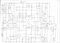
The circuit above is more or less bunk. It works, but not that well. This circuit has been thrown out and a new idea has replaced it. Getting the outputs to stay in phase at higher frequencies can be problematic. This is what steered me towards the bridge topology. As stated above, in the development of my balance bridge power amp, a circuit was needed that could take a single line input and output a balanced +phase AND -phase, both with gain and DC control. This circuit idea has been derived out of that power amp’s conceptual idea. I added a simple J-fet follower as each output. In the power amp, the J-fets form a symmetrical differential of the next gain stage instead of a follower but either way, the load is still the gates of 2 J-fets. I suppose a killer headphone amp could be made by adding more parallel J-fet followers. Don’t really have a need for one but who knows, maybe a future project…
Ra is the load impedance of the +phase VAS, and Rb is the load Z of the -phase VAS. Since the input signal is only to the +input, the -input is driven by the difference from the voltage divider, created by the +phase output feeding back to the -phase input and the 'floating' GND reference. This creates a larger output voltage gain on the +output than the -output if Ra and Rb is the same value. However, when Ra is proportionally smaller than Rb, the two outputs can be made identically equal in magnitude and perfectly opposite in phase, apparently even well up past 1Mhz.
Transistors A-D is a matched array. I used a THAT 340 At 0V input, transistor A conducts to transistor C, just the same, transistor D sinks current from transistor B. The DC servos adjust the DC inputs so as each output is 0VDC. The 0V DC reference is created by separate voltage dividers to the sources of the differential J-fets. When signal is applied and is positive, transistor A conducts into both transistor C and Ra, likewise transistor D sources from both transistor B and Rb. Because the bridge is balanced, the current difference in driving the smaller Ra is placed on Rb via transistor A requiring more current than transistor D. Since transistor B conducts less on behalf of transistor A, that difference in current has to flow into transistor D through Rb, increasing the voltage of the signal across Rb. The result is a sweet phase splitter w/gain. There is a difference in output impedance of +VAS and –VAS, but when driving the gates of a few J-fets, it is of no issue. Little things that affect bias stability such as transconductance and Vbe vs temperature is also of no issue because of the active CMFB bias. At first glance, it seems radically different from most topologies around here, that “too many transistors” comment gets thrown around a lot, but I got it to work....damn well. Thought people might be interested conceptually because a truly good descrete phase splitting circuit can be hard to find, as I have found out.

I may add the resistor values, current flows and parts I used if there is any interest.
Here is the output of the power amplifier that uses this circuit as the front end/control. Notice the perfect phase alignment of both outputs in the top two pictures. The bottom two is the difference, as the load would see. Just as a note, that funky crossover distortion comes from the low bias of the output stage of the amp, but the output of this circuit is void of that, less a gain of about 7.
The circuit above is more or less bunk. It works, but not that well. This circuit has been thrown out and a new idea has replaced it. Getting the outputs to stay in phase at higher frequencies can be problematic. This is what steered me towards the bridge topology. As stated above, in the development of my balance bridge power amp, a circuit was needed that could take a single line input and output a balanced +phase AND -phase, both with gain and DC control. This circuit idea has been derived out of that power amp’s conceptual idea. I added a simple J-fet follower as each output. In the power amp, the J-fets form a symmetrical differential of the next gain stage instead of a follower but either way, the load is still the gates of 2 J-fets. I suppose a killer headphone amp could be made by adding more parallel J-fet followers. Don’t really have a need for one but who knows, maybe a future project…
Ra is the load impedance of the +phase VAS, and Rb is the load Z of the -phase VAS. Since the input signal is only to the +input, the -input is driven by the difference from the voltage divider, created by the +phase output feeding back to the -phase input and the 'floating' GND reference. This creates a larger output voltage gain on the +output than the -output if Ra and Rb is the same value. However, when Ra is proportionally smaller than Rb, the two outputs can be made identically equal in magnitude and perfectly opposite in phase, apparently even well up past 1Mhz.
Transistors A-D is a matched array. I used a THAT 340 At 0V input, transistor A conducts to transistor C, just the same, transistor D sinks current from transistor B. The DC servos adjust the DC inputs so as each output is 0VDC. The 0V DC reference is created by separate voltage dividers to the sources of the differential J-fets. When signal is applied and is positive, transistor A conducts into both transistor C and Ra, likewise transistor D sources from both transistor B and Rb. Because the bridge is balanced, the current difference in driving the smaller Ra is placed on Rb via transistor A requiring more current than transistor D. Since transistor B conducts less on behalf of transistor A, that difference in current has to flow into transistor D through Rb, increasing the voltage of the signal across Rb. The result is a sweet phase splitter w/gain. There is a difference in output impedance of +VAS and –VAS, but when driving the gates of a few J-fets, it is of no issue. Little things that affect bias stability such as transconductance and Vbe vs temperature is also of no issue because of the active CMFB bias. At first glance, it seems radically different from most topologies around here, that “too many transistors” comment gets thrown around a lot, but I got it to work....damn well. Thought people might be interested conceptually because a truly good descrete phase splitting circuit can be hard to find, as I have found out.
I may add the resistor values, current flows and parts I used if there is any interest.
Here is the output of the power amplifier that uses this circuit as the front end/control. Notice the perfect phase alignment of both outputs in the top two pictures.
The bottom two is the difference, as the load would see. Just as a note, that funky crossover distortion comes from the low bias of the output stage of the amp, but the output of this circuit is void of that, less a gain of about 7.Attachments
- Status
- This old topic is closed. If you want to reopen this topic, contact a moderator using the "Report Post" button.