"INA134 and input impedance mismatch "
For the diff to SE conversion in my newest HiFi preamp...
The INA134 datasheet says this about improving CMR, but I'm confused:
This only if you "know" the exact mismatch....but...
What could I do if I "don't know" the mismatch (if any) ??
=RR=
For the diff to SE conversion in my newest HiFi preamp...
The INA134 datasheet says this about improving CMR, but I'm confused:
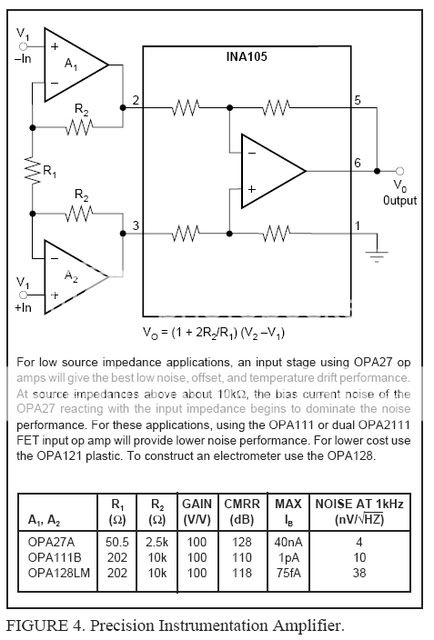
(As shown in Figure 1,) the differential input signal is connected
to pins 2 and 3. The source impedances connected to
the inputs must be nearly equal to assure good commonmode
rejection. A 10 ohm mismatch in source impedance will
degrade the common-mode rejection of a typical device to
approximately 74dB. If the source has a known impedance
mismatch, an additional resistor in series with the opposite
input can be used to preserve good common-mode rejection.
This only if you "know" the exact mismatch....but...
What could I do if I "don't know" the mismatch (if any) ??
=RR=
Hi,
measure the simple bits, the resistors.
The output impedance is a little more difficult but still measurable if you have an oscillator and reasonably accurate DMM with a variety of load resistors.
The most awkward measurement is the cap on each of the lines. They would need to be disconnected and the capacitance measured and corrected if unmatched. Or discarded and replaced with matching caps.
This matching has to go all the way through the balanced line. from source amplifiers to input of ina134.
Matching to better than 0.1% is mimimum and try for 0.01% if you have equipment and technique to achieve that tolerance.
Andrew is right, of course (hi Andrew!) but it may not be necessary. Are you feeding that INA from the balanced output of a source, like a DAC? You may be able to get some info from its manual. Also, the manufacturer would try to make the Zout of both the balanced lines identical, there may be specs for that too. For instance, if you have a source with 600 ohm Zout, it is pretty likely that that Zout has been 'synthesized' with equal, precision, series resistors.
Jan Didden
Jan Didden
The only way to reduce the common-mode error caused by source impedance mismatch is to buffer the inputs.
The error caused is proportional to the ratio between input impedance and source impedance mismatch, if the input impedance is in the megaohms (opamp voltage followers) impedance mismatch effects become negligible.
Basically you have to turn the INA134, which is a differential amplifer, into an instrumentation amplifier (google it).
janneman said:Andrew is right, of course (hi Andrew!) ....... Are you feeding that INA from the balanced output of a source, like a DAC?
I am not sure what will be feeding these balances inputs, probably various units ("pro" CD player, a PC audio soundcard, or other future units).....hence the "don't know" quotient.
Andrew said:The most awkward measurement is the cap on each of the lines. They would need to be disconnected and the capacitance measured and corrected if unmatched.
You mean the output caps on the balanced source unit (cd player, etc) ? I'm looking to correct ANY balanced line, at the input of the preamp I'm building, without having to check/test these sources.
The answer Tim__x gave below, is what I thought might work, because it corrects itself independant of source...I'll have to find a schemo.....this is probably an easy find. I think the INAxxx series datasheets are full of example circuits

Tim__x said:The only way to reduce the common-mode error caused by source impedance mismatch is to buffer the inputs.
The error caused is proportional to the ratio between input impedance and source impedance mismatch, if the input impedance is in the megaohms (opamp voltage followers) impedance mismatch effects become negligible.
Basically you have to turn the INA134, which is a differential amplifer, into an instrumentation amplifier (google it).
=RR=
This perhaps ??
..but with my INA134...
What gain (resistors value) should I use ??
(I am able to match R well, w/ a good HP meter.)
OR this one.....
http://www.jensentransformers.com/an/ingenaes.pdf
=RR=
..but with my INA134...
What gain (resistors value) should I use ??
(I am able to match R well, w/ a good HP meter.)
OR this one.....
http://www.jensentransformers.com/an/ingenaes.pdf
=RR=
OR...
from Walt Jung's book, chapter:"Signal Amplifiers" (analog.com)
...pdf page 42.
http://www.analog.com/library/analogDialogue/archives/39-05/Web_Ch6_final_I.pdf
from Walt Jung's book, chapter:"Signal Amplifiers" (analog.com)
...pdf page 42.
http://www.analog.com/library/analogDialogue/archives/39-05/Web_Ch6_final_I.pdf
Hi,redrabbit said:I am not sure what will be feeding these balances inputs, probably various units ("pro" CD player, a PC audio soundcard, or other future units).....hence the "don't know" quotient..........
You mean the output caps on the balanced source unit (cd player, etc) ? I'm looking to correct ANY balanced line, at the input of the preamp I'm building, without having to check/test these sources.
The main advantage of balanced connects is the improvement in interference rejection.
Throw away that improvement and all you're left with is the extra circuitry between the source and the amplifier.
If you want to retain that rejection advantage then you MUST ENSURE that the impedances are balanced.
You should measure all your balanced outputs for accuracy of matching and if needed bring them up to your minimum standard.
Your receiver/amplifier can be matched at first build but that is a waste if some of your sources are poorly matched. Professional gear, then be professional as a user. They test and set-up everything, often before use every day. The output quality depends on the skills of the technician.
I see an alternative.
Go back to unbalanced and use the minimum of circuitry to achive the highest quality sound and sell off all your balanced gear.
Tim__x said:The only way to reduce the common-mode error caused by source impedance mismatch is to buffer the inputs.
The error caused is proportional to the ratio between input impedance and source impedance mismatch, if the input impedance is in the megaohms (opamp voltage followers) impedance mismatch effects become negligible.
Basically you have to turn the INA134, which is a differential amplifer, into an instrumentation amplifier (google it).
If you are speaking about rejection of inductively and capacitively coupled noise in long audio transmission lines, those statemens about buffering are completely wrong. The whole point of making the impedances to ground of both hot and cold wires equal is to get the same amount of noise picked up by both of them so that it can be cancelled as much as possible by substraction. Unequal impedances cause differential noise pickup resulting in far from optimum cancellation, no matter how good buffers and amplifiers you use.
For short transmission lines where coupled noise is almost negligible, impedance mismatch between hot and cold wires is not that important because noise picked up through ground loops is attenuated by CMRR anyway. Here buffering may be useful only if the differential amplifier actually benefits from equal source impedances.
Note that if you wanted smart line impedance correction, you could use a switchable trimmer for noise nulling by ear...
AndrewT said:
I see an alternative.
Go back to unbalanced and use the minimum of circuitry to achive the highest quality sound and sell off all your balanced gear.
This is pointless. Those -30dB or -40dB of humm and noise that usually result when you have various pieces of (earthed) equipment connected through several meters of unbalanced lines are not exactly what I call "highest quality sound". Add a mixing console (so that the volume is no longer controlled inside the amplifier) and more meters of wiring to the equation and it will get much worse if left unbalanced.
Of course, it's also pintless to use balanced lines in half a meter long wirings with double-insulated non-earthed equipment to cancel a noise that is not there to start with.
Andrew, points taken, and they make sense.
And I will now check the balanced outs of my source(s).
You are reminding me to avoid a system full of "band-aids" and extra electronics.. Which I believe is good advice.
But...I don't see myself messing with (adjusting) their output circuitry (if there's a mismatch)...unless it is physically easily accessible, and it ain't made up of SMD parts!!
EVA said:
You mean on one leg of the hot/cold....like a dip switch for adding resistance, only when necessary ?
For curiousity sake, if one were to employ the instrumentation amp scheme (pic I posted earlier), what would it's overall gain be ??
unity,1,2,....
=RR=
And I will now check the balanced outs of my source(s).
You are reminding me to avoid a system full of "band-aids" and extra electronics.. Which I believe is good advice.
But...I don't see myself messing with (adjusting) their output circuitry (if there's a mismatch)...unless it is physically easily accessible, and it ain't made up of SMD parts!!
EVA said:
Note that if you wanted smart line impedance correction, you could use a switchable trimmer for noise nulling by ear...
You mean on one leg of the hot/cold....like a dip switch for adding resistance, only when necessary ?
For curiousity sake, if one were to employ the instrumentation amp scheme (pic I posted earlier), what would it's overall gain be ??
unity,1,2,....
=RR=
??
If you could please reply, as I'm trying to understand this..
Your help is greatly appreciated.
=RR=
I don't understand your question, the equation is written on your picture
http://i5.photobucket.com/albums/y177/Midiot/INA105bufferedinputs.jpg
you can also read the INA134 datasheet fig. 5, there it is again...
If you want a advice, I really do not know about your application, but line levels are usually high enough.
Any additional gain will reduce the headroom.
So leave out R1 and set R2 to your convenience.
Maybe 1k could be useful for bipolar opamps.
regards
Jürgen
Thanks juergenk.
Yes, I saw the equation, but wondered the "typical" gain amount used here for the "average" line level balanced output. All schematics I've found, only give the equation, but no resistor values, or more precisely...recommended "gain", for audio applications using this instrumentation amp.
Based on your reply, I understand this:
Gain resistor Rg is eliminated (unity gain) and this is typical.
This was my hunch, but needed conformation.
But I will put 2-socket pins on the board...where Rg would normally go, just in case I need to change it. Meantime, a jumper wire across the pins will serve as "unity gain".
thanks.
=RR=
Hi rabbit,
Regards
Jürgen
the frontend would have unity gain without R1, this means an infinte 'air resistor' and not a short.But I will put 2-socket pins on the board...where Rg would normally go, just in case I need to change it. Meantime, a jumper wire across the pins will serve as "unity gain".
Regards
Jürgen
redrabbit said:[snip]And I will now check the balanced outs of my source(s).
You are reminding me to avoid a system full of "band-aids" and extra electronics.. Which I believe is good advice.
But...I don't see myself messing with (adjusting) their output circuitry (if there's a mismatch)...unless it is physically easily accessible, and it ain't made up of SMD parts!!
[snip]
Thta's why I asked about your sources. If you use sources that come with balanced outputs, you can be *reasonably* sure they are really impedance balanced, and the spec sheet/user manual should talk about that.
If it is diy, you need to make sure yourself they are balanced.
Jan Didden
juergenk said:Hi rabbit,
the frontend would have unity gain without R1, this means an infinte 'air resistor' and not a short.
Regards
Jürgen
oops, you're right !!!!

No jumper.
=RR=
Jan...didn't you ask me about those Philbrick dual socket things?
I only have one of each (I forget which, search for the post)....but the surplus store may have more (??) I'll check.
PM me your address, they are now yours !!
redrabbit said:[snip]Jan...didn't you ask me about those Philbrick dual socket things?
I only have one of each (I forget which, search for the post)....but the surplus store may have more (??) I'll check.
PM me your address, they are now yours !!
Hey, great! I'll take whatever you/they have if the price is reasonable. Rather than you shipping them to me across the Great Pond, I'll be in SF for the Burning Amp festival end of october, so I'll get you a local (CA) address. Unless you make it to the BAF , that would even be better! Shake hands with Nelson Pass, anyone?
And we can talk balanced/unbalanced all you like .
")
Jan Didden
PS Send me an email so I can get back to you via PM. Your forum email appears disabled
If you are speaking about rejection of inductively and capacitively coupled noise in long audio transmission lines, those statemens about buffering are completely wrong.
Yes, but I wasn't. I was speaking purely of common mode rejection, not of differential mode noise pickup.
I don't like relying on trims, except where absolutely necessary. You can't deny that, connected to randomly unbalanced source impedances, a high impedance input is a better compromise than an untrimmed low impedance input. Of course your suggestion will give better performance, but it must be retrimmed every time you change source.
Edit: On second thought, your statement does not apply in the case of inducted noise, so long as proper cabling is used.
- Status
- This old topic is closed. If you want to reopen this topic, contact a moderator using the "Report Post" button.
- Home
- Amplifiers
- Solid State
- INA134 and input impedance mismatch