I was just running again the latest sim for the super leach with 3055, and increased the rails to +-70V.
This pushed up the onset of clipping, so thd drops with the same input level and the amp can crank out more power (thd climbs again as it gets closer to clipping of course).
With the rails at 70V and 8ohms resistive load, it can get close to 250Wrms before the onset of clipping makes the thd shoot way up.
The thing is, I also realized it has no limiter and this is going to get a bit interesting, as the choice of locus has to be done judiciously for the stacking of the outputs. It's a little different from regular amps.
After reviewing the available options for limiters and examining more closely the one that I thought might be a good possibility to use (fig49 posted earlier in post #787), I realized that one isn't such a good fit after all.
It has a few drawbacks not so practical for use in the grounded bridge.
1) the grounding between the Rc1 resistors isn't a good idea with the floating rails
2) the use of the D1-Rd sensing isn't practical enough for a multi-pair output stage
3) splitting the R2 adds more parts for no real good reason
Instead, I'm now leaning towards using a slightly modified version of the one from fig44 (attached), which doesn't reference to ground and the R3 sensing can be done on multi-pairs.
The one thing that I would modify on that one from fig44 is the temperature compensated regulated references like used in fig49. That small addition would not alter the way the calculations are done for a limiter as is on fig44.
Attachments
Wow! So that means you're sensing the heat from the sink via the leads and not the diodes' bodies. The length of those leads must be important, affecting the response delay.
What bothers me with using diodes is that flimsy mechanical mounting system.
.
Flimsy mechanical mounting systems = eventual field failures. I’ve had TO-92s with flying leads break off, that’s why the switch to the 126. If you want faster response time use the non isolated TO-126 or a 220. Collector is the tab - probably better than conducting through leads. But then you’ve got to deal with the insulator. Use thin kapton tape, and when it scrapes through, your amp goes up in a shower of sparks. Use a sil-pad or mica and grease, and you’re no better off than using the isolated case type.
Flimsy mechanical mounting systems = eventual field failures. I’ve had TO-92s with flying leads break off, that’s why the switch to the 126.
Definitely! I'm wary of rigging things that way. Even if it works, I'm not trusting it will continue working properly over time and in case of some abuse.
That's why I favor more "permanent" methods.
If you want faster response time use the non isolated TO-126 or a 220. Collector is the tab - probably better than conducting through leads. But then you’ve got to deal with the insulator.
I assume the bd139 types aren't isolated, so there is a need to isolate it from the sink. It does introduce more lag and loses some of the efficiency because of that insulation, but I think that contact with the sink is much more consistent and durable over a long time.
A reliable long term solution feels better than something rigged that could fade over time.
Use thin kapton tape, and when it scrapes through, your amp goes up in a shower of sparks. Use a sil-pad or mica and grease, and you’re no better off than using the isolated case type.
Yes, a proper flat surface contact properly isolated seems better to me than something more round that is clamped by force and pressing on a thin isolator that can fail from the strain.
It's up to the DIYers to make their choice of course. I favor more reliable and permanent methods. That's why I never liked the diodes solution from Marshall Leach. It works, but can fail later, and it's more work to assemble properly.
The thermaltrak parts were a pretty good idea, with nothing extra to mount and there can be no better thermal contact than this.
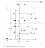
Here is a snapshot of a part of the amp with the added limiter that I'm thinking about using.
Most values aren't calculated yet. I just put an arbitrary 10k there just to let it work and test other things for now.
I realized I will need to lower the value of the caps C24/25 for the purpose of easing the simulation, due to the very long time constant compared to how long the simulation runs. Those caps take about 2.5sec to fully charge, and the sims never run that long, so I think for simulation purposes maybe 1u will do, instead of the 100u used for an actual final build.
I did calculate the res that set the current in the LEDs, which should set it at a little over 5mA. There is no need for more I think.
The current sources don't reference to ground this way, so the rails can swing at will without affecting the voltage references.
That schematic is a little dense, but should be clear enough for now.
Now the proper values need calculating. (the amp's low side has the same thing there)
Attachments
I understood Kapton tape to be pretty tough stuff, I don't think you can pierce that too easily. This arrangement was only meant to be, I feel, an improvement on the commonly used Leach idea of diode bodies in holes, which also used flying leads, and there are a lot of Leach's about.Use thin kapton tape, and when it scrapes through, your amp goes up in a shower of sparks. Use a sil-pad or mica and grease, and you’re no better off than using the isolated case type.
Are you sure about a resin bodied device having an equivalent thermal conductivity to other forms of insulator, as you imply?
Brian
If the diode leads are arranged next to each other and tinned to make them have some flatter surface, maybe it won't be very hard on the insulator to pierce it.
With the clamping, which should be firm, I'm wary of it to remain safe over the long term though.
Perhaps folding the leads several times, next to each other, making them into a much larger surface, and tinned to smooth out that surface, would spread the forces over a larger surface to reduce stresses, while at the same time increasing the thermal contact...
Still, I feel using a part with a metal surface would be more reliable.
That's a choice to be made by each DIYer.
This is good, exchanging ideas on such things.
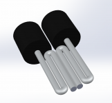
To illustrate what I meant earlier about folding the diode leads to hopefully improve the chances not to breach the insulator with the clamping, I drew up a quick 3D.
The leads should be long enough to fold them this way 3 times to have a wider area to tin and put together with other diodes next to each other this way, the area can be larger to make better thermal contact and reduce somewhat the stresses.
Just some ideas...
The leads should be long enough to fold them this way 3 times to have a wider area to tin and put together with other diodes next to each other this way, the area can be larger to make better thermal contact and reduce somewhat the stresses.
Just some ideas...
Attachments
How many watts RMS will your amp produce at 8 ohms and at 4 ohms?
Which amp are you referring to? The grounded bridge? The super leach?
The grounded bridge with a 70V (rail to rail) supply, if that supply is "stiff" and doesn't sag too much, the power output on 8ohms should get close to 225Wrms. If the psu is really stiff, close to double that much should be fine on 4ohms, but it may be good to go for the 5 pairs version if driving 4ohms.
The super leach (3055 based), with +-70V rails, puts out close to 250Wrms on 8ohms before thd shoots up too much at the onset of clipping.
The grounded bridge with 4 pairs should be fine driving the 4ohms load, as long as the heatsinking is sufficient. The actual load on each amp side would be 2ohms (nominal), resistive. So when driving a 4ohms nominal load that is reactive, each amp side can see much lower than 2ohms load. The limiter may start to act a little before reaching max power in that case, to keep it SOA safe.
What gets rather creepy, is thinking about what the grounded bridge can put out when bridged again...
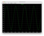
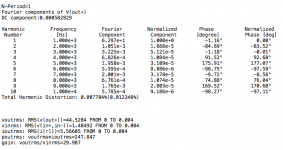
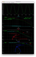
Ok, here is a reading on our latest 4 pairs version of the 3055 grounded bridge.
I disabled the limiter, since almost nothing is calculated yet and it interferes with proper operation as it is right now.
Supply is 70V rail to rail, and I put 0.2ohms of impedance on the supply, so it will sag some under load, as on a real psu.
I pushed the input signal to get closer to clipping without thd climbing. We're at 1khz, on 8ohms (resistive) load.
The clipping happens at a little over 63V and this 2.1Vpeak input level brings it close with a bit over 62Vpeak on the output.
So we're at very nearly 250Wrms @1khz on 8ohms, and we likely would get about that much or a few watts more if we tried edging even closer to clipping.
The thd is pretty good, even at that level, but it is higher at 20khz...
Attachments
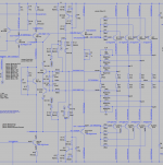
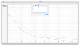
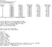
Experimenting with the grapher tool to tweak the 3 slope VI locus, and looking at what voltages are available for zeners without an outrageous price tag, I tweaked the locus to accommodate the SOA at high voltages where 2nd breakdown is an issue.
There are temperature compensated zeners that could be used but they cost a fortune, so I went for the 2% tolerance ones with low cost, like less than $0.25 a pop, and found available voltages that can be used for the locus and only a single zener can set the reference. Those are 500mW zeners, so no problem there.
Using the temperature compensated current source counteracts, at least some, the opposite temperature coefficient from the zeners. Hopefully we can get an overall somewhat neutral temperature drift from the combination.
I tweaked the breakpoints in an attempt to use as much as possible of the "legal" SOA. The SOA plotted is DC derated for Tcase@75C.
Attachments
Which amp are you referring to? The grounded bridge? The super leach?
The grounded bridge with a 70V (rail to rail) supply, if that supply is "stiff" and doesn't sag too much, the power output on 8ohms should get close to 225Wrms. If the psu is really stiff, close to double that much should be fine on 4ohms, but it may be good to go for the 5 pairs version if driving 4ohms.
The super leach (3055 based), with +-70V rails, puts out close to 250Wrms on 8ohms before thd shoots up too much at the onset of clipping.
The grounded bridge with 4 pairs should be fine driving the 4ohms load, as long as the heatsinking is sufficient. The actual load on each amp side would be 2ohms (nominal), resistive. So when driving a 4ohms nominal load that is reactive, each amp side can see much lower than 2ohms load. The limiter may start to act a little before reaching max power in that case, to keep it SOA safe.
What gets rather creepy, is thinking about what the grounded bridge can put out when bridged again...
Which datasheet are you working from? The datasheet I looked at says 60v is the far right of the SOAR curve.
At 60v and at any appreciable temperature, the SOAR is not much above 1A if at all.
Have you thought of placing lots of them in parallel and avoiding the need for any limiting? Say, qty 20 N devices and qty 20 P devices per channel?
If they are inexpensive in bulk as surplus, why not go for overkill on paralleled output devices?
Which datasheet are you working from? The datasheet I looked at says 60v is the far right of the SOAR curve.
Take a peek at that last posting with the SOA and locus plotted together.
We've all been discussing this second breakdown issue with the 3055s for quite some time, and although we're trying not to stray too much away from the datasheet's 60V limit, we do know they can handle more than that, and in the case of those designs we're working on, we're really not going much over the limits, because a supply at 70V when idling, with the sagging under load plus the overhead from losses such as Vcesat, drop in the emitter resistors and the likes, the actual Vce the parts will be exposed to won't be much over the 60V limit, if any.
For those still afraid of slightly breaking that limit, the option is simple, use slightly less than 70V supply, that's all.
A transformer with a 50V secondary, will provide close to the 70V DC supply, and for the wary, just go for a 48V secondary and the supply will be less than 70V and then the parts won't be subjected to anything beyond their datasheet's limits.
At 60v and at any appreciable temperature, the SOAR is not much above 1A if at all.
Obviously. Take a peek at those plots posted earlier.
Have you thought of placing lots of them in parallel and avoiding the need for any limiting? Say, qty 20 N devices and qty 20 P devices per channel?
If they are inexpensive in bulk as surplus, why not go for overkill on paralleled output devices?
Actually they are no longer as cheap as they used to be, if from any reputable sources, and compared to modern much better parts, they can even be more expensive.
The key is to be extremely careful with the sources, as there are so many fakes out there. When buying cheap parts, there is a very high probability that they are fakes. That's the main concern, not the fact we're going slightly over their limits.
And we actually are designing for multiple pairs. The grounded bridge we're working on is 4 pairs, and there is a 5 pair version for those who want to bridge it again (bridged grounded bridge).
The 4 pairs has enough SOA for 8ohms load easily and pretty much can handle 4ohms, even reactive.
With the protections, the 4 pairs version should still be safe if bridged, but to push it to the max, if bridging the bridge is the goal, going for the 5 pairs would be better.
As far the super leach version is concerned, we're using 3 "sets" of outputs (each set is 4 parts), and it can also handle 4ohms loads, for a power output of some 250Wrms as well, with 70V rails.
The rails on the super leach is +-70V, for 140V rail to rail.
The grounded bridge however, uses only a simple single supply with 70V rail to rail, without a center tap.
Just to put it in perspective, the grounded bridge on 8ohms nominal load, can easily put out 225Wrms, even about 250W at onset of clipping if the rails haven't sagged too much.
Once that grounded bridge is bridged again, the power on 8ohms nominal can come to some 1kWrms. With 3055s, it's unheard of, as far as I know.
There is no reason as well not to be able to bridge the super leach, so that solution as well could put out just about as much power.
Have you thought of placing lots of them in parallel and avoiding the need for any limiting? Say, qty 20 N devices and qty 20 P devices per channel?
There is one thing to keep in mind about multiplying pairs of output when they're BJTs: unlike MOSFETS, you can't as easily add more and more pairs without some consequences, without beefing up the previous stage.
The original 3055 based grounded bridge was proposed by John Ellis and had only 2 pairs of outputs, and it was using the BD139/140 as drivers.
We went to 3 pairs, and that one could work with the BD drivers still.
However, when going up to 4 pairs, the BD drivers can get pushed too hard and that's why the beefier MJE15030/31 was chosen instead.
Going to 5 pairs works with the MJE parts as well, but in extreme cases on highly reactive loads at max power on low impedance, we get them real close to their limits.
Going for 6 pairs might be ok, but I would think even beefier drivers should be used then.
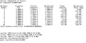
Here is an example. I simulated our 4 pairs grounded bridge with a 4ohms (resistive only) load.
As you can see the current it puts out to the load gets close to 15A (peak), so it wants to start clipping a little earlier than on 8ohms of course.
Not only the supply can sag a little. With the 0.2ohms impedance that I put on this simulation on the supply, we're talking about some 3V of sagging from the 70V, and that could be even more, especially if there is some wiring that's not quite up to par. And that's also why I advocate for an all-in-one PCB for everything, including the psu, complete, on the pcb, so the only wiring left is the transformer leads, which can also be kept as short as possible.
Now much more loss comes from other things, the major part from the emitter resistors on the outputs. We're using 0.22ohms there, and with close to 15A flowing through that, we're already losing close to 3.3V, on each, and since in a bridge, there are 2 of those in series with the load at all times, that's some 6.6V of losses, plus the supply sagging and some other losses, it explains why on such low impedance loads at max power, the clipping happens earlier.
We could go for 0.1ohms emitter resistors, I suppose, but that's less to even out the currents in the outputs, so I don't think it's worth it.
But still, with those losses and the lower clipping, look at the power put out! some 427Wrms (4ohms res load). Not bad I think, and that's with a decent thd as well. (this is at 1khz)
Attachments
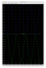
Here is one more example of how the 4pairs grounded bridge fairs on low impedance and some reactive load.
This is at 1khz on 4ohms with a 2uF cap in parallel to the load.
Although it does use up much more of the SOA, this added reactance on the load hardly alters the performance, with still decent thd and same power output.
The protections are still disabled for now, and they must be designed not to act in this type of situation. More reactance can be handled and it can get closer to using up the available SOA.
Attachments
For the purpose of making an amp as bulletproof as possible, not only to protect itself, but also to protect the speakers from the amp as well, and using whatever protection and detection is implemented, I'm thinking a detection of a short on the speaker should be done and used to prevent unmuting and warn about the situation.
Also in that same spirit, a detection of DC from the amp output should be done before unmuting as well.
Any ideas about how to do this would be welcome. Don't forget the use of a SSR to mute the amp's output, and I think it's probably best to place it on the grounded side of the output. What objections are there to place the SSR on the grounded end?
Not too awfully long ago, I built up a simple 2N3055 amplifier running off +/-32V. Powered by a 22-0-22 650 VA toroid meant to power 12 gainclones simultaneously. Simple diff pair, single ended VAS with a 6 mA current source, and the same output triple used in the Phase Linear, with 3 actual 2N3055’s per bank. It had absolutely no trouble with a 2 ohm load - that is, 4 speakers in parallel, turned up to abusive levels. I really don’t think you’ll need to go to 5 transistors per bank.
- Home
- Amplifiers
- Solid State
- Amplifier based on 2N3055