All these post3040 devices seem quite attractive to try out as input devices for a Power Amplifier.
The 2sk932 and 2sk3557 have ratings of 15V and 200mW.
This virtually demands a cascode to reduce exposure to voltage and power.
And gives the advantage of reducing the input capacitance.
Are there any particular implementation rules that would get the best out of these devices? I'm thinking what Vds? what Idss?, what Id relative to Idss? what degeneration resistor values in the source? What input impedance (RF capacitance || Rin)?
Re: input impedance...
Crss is about 3pf, and Ciss is about 10pf. Since the JFET has fairly low maximum vds, using cascode is likely a good thing anyway... This would give you an approx 15-30pf input capacitance with cascode (just estimating, probably a bit high.) Cascode tends to be a generally good idea on this kind of transistor given the low vds max and the fact that linearity is generally improved (eliminating the effect of changing output resistance), and it really helps to keep the nonlinear effects of input capacitance under control. Using a JFET as the cascode transistor might have some generally small noise benefits relative to BJT, but those benefits aren't signficant. Using a BJT would be helpful because of wider component characteristic choice, generally lower capacitances, and easier to map bias voltage on the base vs. the drain voltage on the input JFET. With a BJT, you can count on -.6-.-7 volts difference, with a JFET it would likely be approx +0.5-whatever. I would tend to use a moderately high Beta, true low noise BJT myself. I'd tend to bias the 2nd transistor tradeoff for low capacitance/high beta/low noise and consider rbb' as a second consideration in this limited case.
Crss is about 3pf, and Ciss is about 10pf. Since the JFET has fairly low maximum vds, using cascode is likely a good thing anyway... This would give you an approx 15-30pf input capacitance with cascode (just estimating, probably a bit high.) Cascode tends to be a generally good idea on this kind of transistor given the low vds max and the fact that linearity is generally improved (eliminating the effect of changing output resistance), and it really helps to keep the nonlinear effects of input capacitance under control. Using a JFET as the cascode transistor might have some generally small noise benefits relative to BJT, but those benefits aren't signficant. Using a BJT would be helpful because of wider component characteristic choice, generally lower capacitances, and easier to map bias voltage on the base vs. the drain voltage on the input JFET. With a BJT, you can count on -.6-.-7 volts difference, with a JFET it would likely be approx +0.5-whatever. I would tend to use a moderately high Beta, true low noise BJT myself. I'd tend to bias the 2nd transistor tradeoff for low capacitance/high beta/low noise and consider rbb' as a second consideration in this limited case.
Posts 9, 12 & 15 use a remote server to host the pics.
Your latest pic is an attachment using the Forum as your host.
Everyone who is still a Member gets to see your attachment for as long as this Forum exists.
For some unknown reasons the Forum will not ban the use of remote servers linked to this Forum.
Your latest pic is an attachment using the Forum as your host.
Everyone who is still a Member gets to see your attachment for as long as this Forum exists.
For some unknown reasons the Forum will not ban the use of remote servers linked to this Forum.
Pavel, this is a good question, but I was not really oversimplifying. This issue was covered in Section 1.5 of my MOSFET amplifier paper. The gate-source capacitance is bootstrapped by the output, so if the source follower gain is, say, 0.9, the 700 pF or so of Cgs is effectively reduced to about 70 pF. Then remains the gate-drain capacitance of about 100 pf. Together they amount to an effective capacitance of about 170 pF, thus requiring about 17 mA to support a voltage slew rate of 100 V/us.
Looking at the input capacitance of a device by itself can be very misleading. A lot of people express concern about the input capacitance of MOSFETs when they don't realize how big the effective input capacitance of a bipolar transistor is. Consider a ring emitter transistor with an ft of 30 MHz and operating at 1 amp. What do you think the effective input capacitance is? It is a whopping 0.2 uF! Just remember that the hybrid pi input capacitance of a bipolar transistor is transconductance in Siemens divided by 2*pi*ft. The transconductance at 1 amp is 40 S. Even though this may seem not to be a "physical" capacitance, it matters every bit as much. The thing that mitigates the effect of this capacitance is the same thing that mitigates it for a MOSFET: in an emitter follower configuration the hybrid pi capacitance is bootstrapped to a much smaller effective value.
What I really meant about high current drive required for bipolar output stages was that required under high output current conditions when there is beta droop in the output stage. In some cases, you can have an output stage delivering 10 amps to the load under conditions where the beta has drooped to 20 or less. In this case the driver needs to supply over 500 mA to the output devices. THIS is what I meant by high drive current. I've seen cases where the bipolar drivers go into secondary breakdown before the output transistors.
Cheers,
Bob
Thats probably one of the reasons why krell is using Dual TO264 drivers per rail in each half of their balanced amplifier. One I think they are running at very high idle current probably to overcome the cross conduction and other to deal with the beta droop.
If IPS is same for both BJT and MOSFET OPS then how does it perform in sub bass? Many say and also almost all pro amps which are in AB or H use Bipolars and mosfets hardly seen in pro applications. I think there is something that Bipolar does that Mosfet cannot do at very low frequencies?
@ Bob Cordell
Dear Bob
While reading your book (second edition routledge) I found an alternative to zener gate protection for mosfets in page 341.
I find the natural current limiting provided by the flying catch diodes apealing but could not make it work in my latest lateral mosfet power amp.
Does this method work with laterals ?
Attachments
I found this pdf in your site but it uses a different current limiter... not the flying catch diodes.
http://www.cordellaudio.com/poweramp/DH-220C_MOSFET_Power_Amplifier.pdf
I saw the flying diodes in your BC1 amp but it uses four diodes...... how many should I use for a lateral output stage ?
http://www.cordellaudio.com/poweramp/DH-220C_MOSFET_Power_Amplifier.pdf
I saw the flying diodes in your BC1 amp but it uses four diodes...... how many should I use for a lateral output stage ?
Bob: I like both the 220C and and BC-1 designs. In fact I have the 220C pcbs and will order the bc-1 pcbs when they become available. I have noticed neither of these designs use the D. Self named "Inclusive Compensation" (Linear Audio Vol.0). I seems to offer so much for so very little cost. Since you undoubtedly have the best SPICE simulations of these amplifiers, aren't you a teeny bit curious to see how this sort of compensation changes the HF distortion character of these amps?
The arrangement for the laterals in the DH-220C uses two diodes and two 10-V zeners. This is largely because it takes significant gate voltage to turn them on to full current. Also, in the DH-220C, the laterals should have gate voltage protection, as some laterally actually do internally. Gate-source voltage of more than 15-20 volts can punch through the gate and destroy the transistor.I found this pdf in your site but it uses a different current limiter... not the flying catch diodes.
http://www.cordellaudio.com/poweramp/DH-220C_MOSFET_Power_Amplifier.pdf
I saw the flying diodes in your BC1 amp but it uses four diodes...... how many should I use for a lateral output stage ?
Cheers,
Bob
Bob: I like both the 220C and and BC-1 designs. In fact I have the 220C pcbs and will order the bc-1 pcbs when they become available. I have noticed neither of these designs use the D. Self named "Inclusive Compensation" (Linear Audio Vol.0). I seems to offer so much for so very little cost. Since you undoubtedly have the best SPICE simulations of these amplifiers, aren't you a teeny bit curious to see how this sort of compensation changes the HF distortion character of these amps?
The compensation you refer to is properly called Transitional Miller Compensation (TMC) and was named and popularized by Edmond. You are right, TMC offers tremendous bang for the bu
The compensation you refer to is properly called Transitional Miller Compensation (TMC) and was named and popularized by Edmond. You are right, TMC offers tremendous bang for the bu
My computer burped, and sent the post out mid-sentence.
TMC offers tremendous bang for the buck, and definitely would work with the BC-1. I may have even tried it, but I just don't remember if I did. I also tried the DoubleCross output stage on the BC-1 with encouraging results. Actually, the BC-1 is not a very sophisticated design. In fact, it was just the starter construction example design in Chapter 4 of my second edition. The BC-1 would have come out sooner, but it was behind the DH-220C development.
Cheers,
Bob
Darn, and I thought I was done looking at amp design. Just put my modified DH120 back in service. WAY sweeter than the Parasound 2125 I was suffering with. Converted it to Miller compensation and Exicon outputs. Tweaked the IPS and VAS current. Still Erno's topology. The Exicons were a result of getting carried away before I had a variac. MOSFET bandwidth is well deserved. I dropped the ripple in half using 8 6800 caps. Bigger rectifier of course.
Sony VFET integrated, Sanyo Plus 55, B&K 120, several DH220's and now my modified DH120. Yea, I am a MOSFET fan. I was thinking about an Atoll before I serviced the old Haf.
Adding IPS CM degen and stiffer CCS, 2 pole Miller it can eek out a few less dB distortion, but I am not taking it off the system to do so. It sounds too nice.
2 pole gave slightly better margin at zero gain. A couple degrees. At least by Spice. VAS and IPS rails can be cleaned up by splitting the 47 Ohm with a pair of 22's and adding a second 100u cap. On paper at least.
A test if understand, the output inclusive would be more useful in a BJT than MOSFET. I THINK I understand the same for current feedback. Solves issues that are not as bad with a MOSFET to start with. Do I have a clue?
The 220C is a way more complex amp. I wonder, the original, once ditching the VAS output loading compensation, is so good, is it worth the effort?
Sounds like you've been busy! I'm glad to hear you've had a good sonic experience with MOSFETs.Darn, and I thought I was done looking at amp design. Just put my modified DH120 back in service. WAY sweeter than the Parasound 2125 I was suffering with. Converted it to Miller compensation and Exicon outputs. Tweaked the IPS and VAS current. Still Erno's topology. The Exicons were a result of getting carried away before I had a variac. MOSFET bandwidth is well deserved. I dropped the ripple in half using 8 6800 caps. Bigger rectifier of course.
Sony VFET integrated, Sanyo Plus 55, B&K 120, several DH220's and now my modified DH120. Yea, I am a MOSFET fan. I was thinking about an Atoll before I serviced the old Haf.
Adding IPS CM degen and stiffer CCS, 2 pole Miller it can eek out a few less dB distortion, but I am not taking it off the system to do so. It sounds too nice.
2 pole gave slightly better margin at zero gain. A couple degrees. At least by Spice. VAS and IPS rails can be cleaned up by splitting the 47 Ohm with a pair of 22's and adding a second 100u cap. On paper at least.
A test if understand, the output inclusive would be more useful in a BJT than MOSFET. I THINK I understand the same for current feedback. Solves issues that are not as bad with a MOSFET to start with. Do I have a clue?
The 220C is a way more complex amp. I wonder, the original, once ditching the VAS output loading compensation, is so good, is it worth the effort?
I think TMC is equally effective for BJT and MOSFET amplifiers.
I'm not a fan of CFAs and have never built one, so I can't really speculate whether TMC is more useful for BJT CFA designs.
Cheers,
Bob
Hello Bob
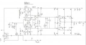
Just finished building my version of the DH220C using the excellent LSK489B and LSJ689B for the IPS.
IPS current is set by a resistor placed between the emitters of the jfets.
I am not using a servo so there is a DC null cap in the NFB circuit.
VAS current is stabilized by 4k7 resistors shunting the collectors of the positive and negative mirrors.
The amplifier works and all currents and voltages are near simulated values with an average difference of 2%
Current on the IPS jfet emitters is very stable as well as current in the VAS buffers.
Simulated current in each VAS is 12mA but in my build it is never super stable.... It fluctuates between 12,7 and 12mA changing 0.1mA each second.
Increasing the shunt resistors (R58 and R59 in my build), does reduce THD but VAS current is even more unstable.
Is this behaviour normal ?
What should I do to completely stabilize VAS currents ?
Best
Ricardo Cruz
Attachments
Can you add a resistor from base Q4 to base Q6 to flow current few micro ampere? Around 10uA, i think is enough.Simulated current in each VAS is 12mA but in my build it is never super stable.... It fluctuates between 12,7 and 12mA changing 0.1mA each second.
No. Between base VAS buffer NPN to PNP. The value around 10 mega ohm depend on PSU voltage. It is better using constant current source, but because the current need is very small, it can use resistor.You mean between bases of VAS and VAS buffer right ?
- Home
- Amplifiers
- Solid State
- Bob Cordell Interview: BJT vs. MOSFET