Hi guys....I am looking for a simple Power amp output stage schematic useing a couple Tip31c/32c Med power Transistors.....
This should drive an 8 ohm speaker and doesn"t need to be especially low noise or anything as it will be for a small Practice guitar amp for a friend.....
I would like it to run off of a Dual supply anywere in the +/-15v to +/-35v range as I would like to avoid the use of an Output Cap.....
If someone knows of a Link to a simple design of can quickly draw me up a simple schematic I would be very greatfull.....
Thanx a Lot guys.....
Cheers
The Dx amplifier can fit your needs...just inform the supply voltage that is your
choice and i will arrange the schematic to adapt your needs.
Give a look in that thread....in this same page you post this one, and observe if you like the simple amplifier.
If you got a positive decision...give me the supply voltage and i will make the modifications to you..... well...TIP31 has voltage limits and power limits...the supply must be inside that transistor power capacities.
http://users.tpg.com.au/users/gerskine/dxamp/
regards,
Carlos
Hi ,Thanx a Lot....
That design looks Nice but it is a Little bit too complex for what I want to do Pluss I don"t have most of those Parts......
I allready have a high gain Guitar preamp design that I am useing (a Simple Opamp configutarion) and I only need at max about 25w or as low as 15w so all I really need is a simple Power stage that has a Fixed Gain......
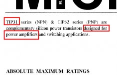
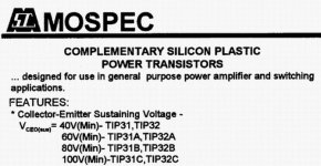
The transistors I have available are...
Tip31C Med power NPN (one)
Tip32C Med Power PNP (one)
2Sb367 Med Power PNP(GE-Metal Can) (four)
http://www.datasheetarchive.com/datasheet.php?article=3692320
Low power (Lots of each)
BC550C NPN
BC560C PNP
2N4401 NPN
2n4403 PNP
2n3904 NPN
2N3906 PNP
N-JFets
2n4416
j201
2n5484
2sc170 (one)
I got lots of Caps/Resistors/Diodes ect.....
As for a Power source I have one 50vA 2x15v Torroid, One 100vA 18v,0v,18v Torroid, and one 160vA 28v,0v,28v EI core....I would like to use the 50vA torroid because I think the other ones are a bit overkill......
I don"t need anything that is very good quality as it will be for electric guitar and as simple as possible would also be a bonus as it will be in a bit of a small space......
If you have any Ideas that would be great.....
Thanx a Lot...

That design looks Nice but it is a Little bit too complex for what I want to do Pluss I don"t have most of those Parts......
I allready have a high gain Guitar preamp design that I am useing (a Simple Opamp configutarion) and I only need at max about 25w or as low as 15w so all I really need is a simple Power stage that has a Fixed Gain......
The transistors I have available are...
Tip31C Med power NPN (one)
Tip32C Med Power PNP (one)
2Sb367 Med Power PNP(GE-Metal Can) (four)
http://www.datasheetarchive.com/datasheet.php?article=3692320
Low power (Lots of each)
BC550C NPN
BC560C PNP
2N4401 NPN
2n4403 PNP
2n3904 NPN
2N3906 PNP
N-JFets
2n4416
j201
2n5484
2sc170 (one)
I got lots of Caps/Resistors/Diodes ect.....
As for a Power source I have one 50vA 2x15v Torroid, One 100vA 18v,0v,18v Torroid, and one 160vA 28v,0v,28v EI core....I would like to use the 50vA torroid because I think the other ones are a bit overkill......
I don"t need anything that is very good quality as it will be for electric guitar and as simple as possible would also be a bonus as it will be in a bit of a small space......
If you have any Ideas that would be great.....
Thanx a Lot...
The Dx amplifier can work with many voltage and can use many kind of transistors
including those ones you mentioned.
The schematic is attached..... if you like it , go ahead...if negative... I trully hope you can find, and fast, something that match your needs.
If need some help..go to Dx tread...my thread...and you will have the help you need.
This amplifier, adjusted to your transistors, will need supply of 22 pulus 22 volts DC...this will make it produce something alike 20 watts RMS over 8 ohms...and may reach the TIP31/32C dissipation limit when using 4 ohms.(dangerous with 4 ohms...may burn if receive loud signal..constant distorted guitar at the input when driving 4 ohms... this will be a burn test...)
Even the 8 ohms speaker, has peaks and valleys of impedance...so... even using 8 ohms speakers you may have problems if the transistor dissipation is not good to work...say...to 4 ohms loads too.
To perceive power increase in one amplifier you will need to multiply the power 4 times...just to perceive something...so...a 20 watts amplifier will sound almost the same into human perception than a 70 watts amplifier.
This amplifier will need adjustments to work with smaller voltage then the designed one.
VR1 will need to be adjusted to 8150 ohms..this is to reduce the offset, that output residual voltage, to 3 to 5 milivolts.
The bias to be adjusted must be around 40 to 50 miliamps
R10 must be substituted to a 3K9 unit
The voltage amplifier, Q3, can be BD139 or TIP31C
The upper transistors, driver and output, Q5 and Q7 will be TIP32C
The lower transistors, the ones at the negative power rail, Q4 and Q6 will be TIP31C
All electrolitic condenser can be 25 volts.... the exception is C12..this one will need to be 50 volts.
Do not feel shy if dislike this amplifier...no problem... i love to cooperate..even if the guy give up related my design.
regards,
Carlos
Attachments
Negative...my fixed idea is my amplifier...let's wait someone will match, exactly
your needs..but really near the impossible, as your needs are very special..and to combine the parts you have will be very hard.
You are needing assistance to an entire project...referenced in our parts....hehe...hard that.
But there are good folks in this forum able to do that and more difficult challenges than that.
To do that i am completelly non competent.
regards,
bye
Carlos
Thanx a Lot....That design looks good....What can I use as a replacement for the 2n5401 and 2sc5200/2sa1943 BJT"s??
It is just that were I live you can"t just go out and buy a couple transistors as there aren"t any good electronics stores even within driveing distance (I would have to take a Plane or take a ferry) so getting specific parts is rather difficult unless I order on line which in this case would take a long time....
Thanx
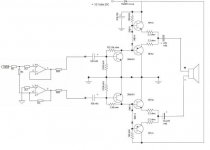
Hi.... I came up with this design and I was wondering if you think it would work OK??
I know it only runs off of a single supply but I was wondering if you could tell me first if this would work?? and secondly if it would be possible to change it to run off of a Dual supply and how to do that and what would have to be changed to make it run at a higher Voltage (20v-24v)......
I basicly have a opamp at the input to act as an Inverter and with each side of the Transistor amp pushing +/- into the speaker....
I don"t know if it will work so I thought I would ask you folks.....
Thanx
Attachments
You could probably knock up a basic Lin design using the parts you have. Something like http://www.ampslab.com/c70.htm would be what you're looking for, I think.
I don't really think TIP31C/32C are suitable for outputs. You'd need more than one pair in any case.
Thing is you really need some medium power devices as VAS transistors (Q4 and Q5 on the C70 schematic). BD139/140 or MJE340/350 would do and are quite common.
You would be best trying to get some TIP2955/3055 or perhaps even the TO-3 versions as outputs, and use the TIP31C/32C as the drivers (Q7 and Q8). The 2N3904 could be used for Q1, Q2 and Q3 with no problems.. and possibly also as Q6 although that might require altering the values of R12/R13/R14.
Not the power level you like Jaycee...but for sure it is output units.
They were used in thousands amplifier models around the world ..including your country sold many Kits using it in the past...even today you have Radio Shack models using it into the output.
Of course, now a days, the power levels forum folks prefer, it will be more suitable as drivers.
Yeah!..i have understood what you mean...but there are beginners that may understand your message as final words...some of them may send TIP31 to trash box...when those transistors can be used.
Maybe not the power level you respect, the power level you like, the power level you prefer..but for sure it is a power output transistor.
regards,
Carlos
Attachments
I guess they could be used... indeed I have seen old power amps using similar transistors, but they were only 15W or so, and not on 4 ohms.
I guess if that's all you had, then yeah it could work... but some medium power devices like MJE340/350 or BD139/140 are still a must, really. Maybe you could run a few of the small signal transistors in parallel to provide enough drive current?
I guess if that's all you had, then yeah it could work... but some medium power devices like MJE340/350 or BD139/140 are still a must, really. Maybe you could run a few of the small signal transistors in parallel to provide enough drive current?
Well I do have some other Transistors but a lot of them are Germanium transistors or disconued and none are high power but I really don"t need high power...
NEC A636
NEC C1098
(2S?)C711
C871
C945
C458
2SB77A
2SB459
2SA353
2SC968
2SC971
Are any of these Usefull??
Also did anyone look at the schematic I posted above?? Does it look like a working curcuit??
Thanx
NEC A636
NEC C1098
(2S?)C711
C871
C945
C458
2SB77A
2SB459
2SA353
2SC968
2SC971
Are any of these Usefull??
Also did anyone look at the schematic I posted above?? Does it look like a working curcuit??
Thanx
Try a variation of the buffered op-amp in DIB's website:
http://www.dibsplace.com/dibsed/CIRCATS/audbuf.pdf
While a great design, it can be simplified greatly and its output capability increased to meet your needs.
1) Replace the MJE182 with 1 x TIP31C (darlington) and 2 x TIP31C (paralleled)
2) Replace the MJE172 with 1 x TIP32C (darlington) and 2 x TIP32C (paralleled)
3) Reduce the emitter resistors to 0.47 ohms
4) And, if you're not up to the bias circuit or lack the parts, replace Q2, R6, R9, and R12 with 4 x 1N4004 diodes.
5) Even simpler, eliminate all components between the op-amp output and the darlington Base connections and run the circuit Class B.
6) IF you use an NE5532 op-amp like the schematic, you can run the power supply rails at +/- 20VDC as the 5532 max is +/- 22VDC.
Minimum parts count, okay performance and sound, and perfect for a small guitar amp.
- Status
- This old topic is closed. If you want to reopen this topic, contact a moderator using the "Report Post" button.
- Home
- Amplifiers
- Solid State
- Looking 4 a simple NPN/PNP Output stage schematic useing Tip31C/32C Transistors??