I am trying to simulate a single-driver DRS-ripole enclosure as a 6-th order bandpass box. I am getting the resulting graph in Hornresp that is quite different than those in Basta, WinISD and VituixCAD using the same input data. My DIY speaker experience is very limited and I don't know what I am doing wrong, so any advice will be appreciated.
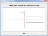
Here is the top view of the planned enclosure (yes, it would be drastically small):

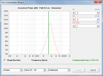
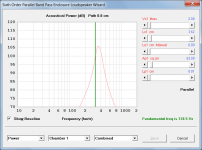
Hornresp:

Basta:

WinISD:

VituixCAD:

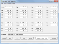
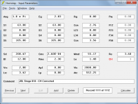
Here is the Hornresp record:
View attachment Bandpass_Hornresp.txt
I tried to follow the Rudolph's suggestion about ripole simulations:
Here is the top view of the planned enclosure (yes, it would be drastically small):
Hornresp:
Basta:
WinISD:
VituixCAD:
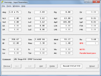
Here is the Hornresp record:
View attachment Bandpass_Hornresp.txt
I tried to follow the Rudolph's suggestion about ripole simulations:
Since there are no custom-made simulation applications for w-/n-baffles (yet), these di/ripoles are best simulated as either a front loaded horn with a vented rear chamber (if a vent can´t be simulated make the rear chamber as big as possible) or as a 2-ported band pass box. The trick is to give the horn or the reflex tube exactly the mouth/throat/tube area and the length of the di/ripole chambers.
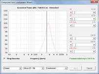
Thanks for suggestion. With CH I get more similar shape of graph to other programs, but its peak is shifted both horizontally (100 Hz) and vertically (10 dB):


And I still don't understand why its bandpass result is different then in other programs.
By the way, I found that I entered Cms in mm/N in first example as every other program requires, but Hornresp is expecting m/N. However, even with that corrected for bandpass, the graph is still quite different.


And I still don't understand why its bandpass result is different then in other programs.
The other programs all use similar, relatively simple models that perhaps have difficulty in handling the unusual port and chamber sizes specified in your design (see attachment). The post linked below may also be of interest.
https://www.diyaudio.com/forums/subwoofers/119854-hornresp-1255.html#post6857875
The only way to know for sure would be to build the system and to measure its performance
") .
.Attachments
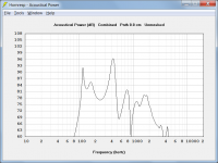
To further check the validity of the Hornresp BP6P model, the results have been compared against those produced by Dr Kolbrek's HornCAD simulation software. The power responses are effectively identical, as shown in the attachments.
Attachments
Here is another test, this time with even smaller enclosure with 8" driver:

Hornresp_Nd - Front loaded conical horn:
View attachment JBL Stage 810_Nd.txt

Hornresp_CH - Normal driver compound (with rear and throat chambers):
View attachment JBL Stage 810_CH.txt

Hornresp_CH2 - Normal driver compound (without rear and throat chambers):
View attachment JBL Stage 810_C2.txt

Hornresp_BP - Sixth order parallel band pass:
View attachment JBL Stage 810_BP.txt

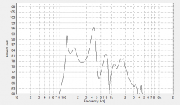
All together (Basta, VituixCAD and 4 x Hornresp):

Basta and VituixCAD are quite similar. "Hornresp_Nd - Front loaded conical horn" and "Hornresp_CH - Normal driver compound (with rear and throat chambers)" are identical, but quite different then other two variants, and none of them is close to Basta/VituixCAD.
Hornresp_Nd - Front loaded conical horn:
View attachment JBL Stage 810_Nd.txt
Hornresp_CH - Normal driver compound (with rear and throat chambers):
View attachment JBL Stage 810_CH.txt
Hornresp_CH2 - Normal driver compound (without rear and throat chambers):
View attachment JBL Stage 810_C2.txt
Hornresp_BP - Sixth order parallel band pass:
View attachment JBL Stage 810_BP.txt
All together (Basta, VituixCAD and 4 x Hornresp):
Basta and VituixCAD are quite similar. "Hornresp_Nd - Front loaded conical horn" and "Hornresp_CH - Normal driver compound (with rear and throat chambers)" are identical, but quite different then other two variants, and none of them is close to Basta/VituixCAD.
"Hornresp_Nd - Front loaded conical horn" and "Hornresp_CH - Normal driver compound (with rear and throat chambers)" are identical, but quite different then other two variants
If you look closely, you will see that your "Hornresp_Nd - Front loaded conical horn" and "Hornresp_CH - Normal driver compound (with rear and throat chambers)" responses are not identical. The peaks are at different frequencies and have different magnitudes.
The BP6P model has internal end corrections on both port tubes.
The Nd model has an internal end correction on the port tube specified by Ap and Lpt.
The CH model has no internal corrections.
To compare "like-with-like":
1. Add an appropriate internal end correction to L12 in the Nd design.
2. Add appropriate internal end corrections to L12 and L56 in the CH design.
3. Change Lp1 and Lp2 values in the BP6P design from 23.50 to 0.01.
The results for all three designs will then be completely identical, as shown in the attachments.
Your "Hornresp_CH2 - Normal driver compound (without rear and throat chambers)" design is nothing like the other three in that there are no chambers present, so obviously the results for that system will be quite different.
There is probably little to be gained by doing any further such comparisons. Rest assured, Hornresp results are entirely consistent across the Nd, CH and BP6P models when correctly specified.
Attachments
Last edited:
Thank you very much for your time and patience with me!
Now I am getting much closer results with other programs. I was confused with Rudolf's suggestion that "The trick is to give the horn or the reflex tube exactly the mouth/throat/tube area and the length of the di/ripole chambers." So, I was using the chamber depth for the port/horn length in some models, while it seems that it should be the width of the material of the enclosure, which will be 25 mm in my case.
I am sorry for a dumb question, but how did you determine L12 in the Nd design and L12 and L56 in the CH design? I suppose it is something related to the internal end correction on the port tube, right? But how Hornresp determines the internal end correction? If it is related to the port area/width, is it calculated for round ports and what if port/slot is rectangular?
Thanks for your suggestion, but I already tried it and I cannot get what I want since S1 cannot be set the same as S2 if S3 is equal to S4 and vice versa.
I am fine with the other three methods, I just would like to know hot to determine the effective length of the ports/horns, i.e. how is the end correction determined.
I am fine with the other three methods, I just would like to know hot to determine the effective length of the ports/horns, i.e. how is the end correction determined.
But how Hornresp determines the internal end correction? If it is related to the port area/width, is it calculated for round ports and what if port/slot is rectangular?
The internal unflanged end corrrection length is given by 0.1952 * Pi * Rp where Rp is the equivalent radius of the port.
For a rectangular port of width W and height H the equivalent radius Rp is given by Sqrt((W * H ) / Pi).
- Home
- Design & Build
- Software Tools
- Inconsistent bandpass enclosure simulation in Hornresp vs Basta, WinISD and VituixCAD