Hello!
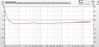
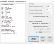
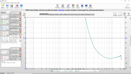
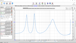
I've been using REW to measure the impedance of my home made speaker drivers. The impedance curve I get has the correct shape (the Fs is correct), but the problem is that the impedance itself is unrealistically low for an Re=5.4ohm driver, as can be seen in the picture attached.
I have calibrated the measurement setup the way that it is instructed in the REW impedance measurement manual. I have also measured the Rleads by making a measurement without any load. Is there anyone who would have encountered this problem before?
I'm using PreSonus AudioBox USB 96 sound card and it's own ASIO driver, and I have checked many times that there should be no errors in the connections. I was already able to find the Vas with the Fs of these results, but I want to find the optimal enclosure volume for my drivers, and to do that, I need the Q parameters. If I have understood it correctly, the maximum value of impedance is necessary to be known when calculating Q parameters.
Attachments
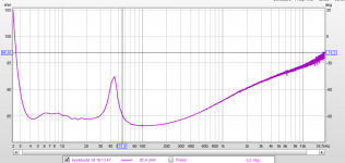
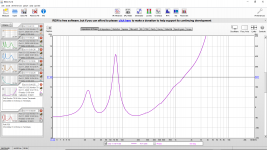
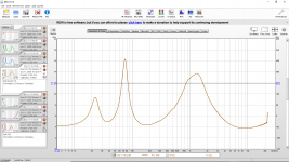
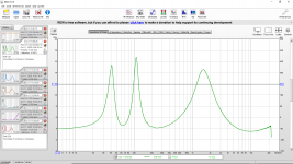
Update: I tried to "calibrate" the system again in a different way, but I don't know if it makes any sense. I replaced the speaker with a 96,1ohm resistor, and I tweaked the Rsense number in REW, so that the impedance curve of that load would be almost a straight line at 96,1 ohms. Then I replaced the resistor again with the speaker. Now the peak in the resonant frequency looks much more realistic. However, now the impedance curve seems to be too high.
I have now idea, if this way of "calibrating" the system makes any sense.
I have now idea, if this way of "calibrating" the system makes any sense.
Attachments
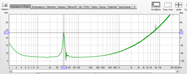
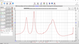
UPDATE: I tried the ARTA LIMP circuit and it worked, both on LIMP and REW. However, when I calculate the Qts based on these results, I always get something from 1.3 to 3. Which I think is usually too high for any reasonable enclosure size  . LIMP gives a Bl of only 4.4Tm, even though I have a super strong neodymium magnet (can lift about 40kg) and a 5,4ohm underhung voice coil. Maybe my coil gap is too wide (2,5mm).
I will still ask for my friend to borrow DATS V2 to check if there was still some mistake in these measurements (I really hope so)...
There may be some problem in my soundcard, which probably was the reason for the first problem. It only has two mono inputs and no stereo inputs, and maybe that's why I didn't succeed at first try. Hence, I had to tweak the setup to fit to my soundcard inputs.
Even though I was the only one to reply my own thread, maybe someone who encounters the same problem can find this information useful.
. LIMP gives a Bl of only 4.4Tm, even though I have a super strong neodymium magnet (can lift about 40kg) and a 5,4ohm underhung voice coil. Maybe my coil gap is too wide (2,5mm).I will still ask for my friend to borrow DATS V2 to check if there was still some mistake in these measurements (I really hope so)...
There may be some problem in my soundcard, which probably was the reason for the first problem. It only has two mono inputs and no stereo inputs, and maybe that's why I didn't succeed at first try. Hence, I had to tweak the setup to fit to my soundcard inputs.
Even though I was the only one to reply my own thread
, maybe someone who encounters the same problem can find this information useful.Attachments
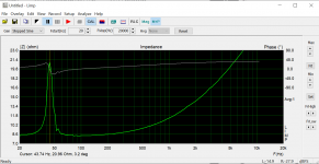
I don't know if this will help but this is my experience:
I started with clip leads and ended up measuring and repairing/soldering the clip leads. I only used the ones that ended up measuring less than 0.1 Ohms. (Not cheap or thin. Soldered, not crimped.)
I used an 8 Ohm sense resistor. I suggest not measuring the speakers until you obtain good results from measuring a known 4 Ohm dummy load resistor (or 8 Ohm or 2 Ohm) instead of a speaker. I found that I had to reverse the sound card input (left and right) leads.
I have attached screenshots of example results.
I recommend low resistance (short and thick leads) and good quality connectors.
Attachments
-
 20201011 REW Speaker Impedance Test Polk Monitor 70 Bi-Wire Upper Terminals.png142.6 KB · Views: 62
 -
 20201011 REW Speaker Impedance Test Polk Monitor 70 Bi-Wire Lower Terminals.png168.4 KB · Views: 55
 -
 20201011 REW Speaker Impedance Test Polk Monitor 70.png157.9 KB · Views: 57
 -
 20201011 REW Speaker Impedance Test Polk CS2.png160.6 KB · Views: 65
 -
 20201011 REW Speaker Impedance Test Polk CS1.png159.5 KB · Views: 72
 -
 20201011 REW Speaker Impedance Test 4 Ohm 100W Resistor.png162.6 KB · Views: 73
 -
 20201011 REW Speaker Impedance Test Polk R50.png157.4 KB · Views: 63
Last edited:
- Status
- This old topic is closed. If you want to reopen this topic, contact a moderator using the "Report Post" button.
- Home
- Design & Build
- Software Tools
- REW measured impedance too low