I need to correct this. To select "Approximation of open radiation condition" is not correct solution for OB.I find solution for OB.
If I use only one subdomain and parameters for domain are: Exterior and Approximation of open radiation condition is selected, then I get also reasonable dipole peaks and minimums.
I understand form Jörg, that also for OB is correct to create two subdomains, interior and exterior and interface between them. Only I had not take clear jet exactly in what form and where in the model interface between subdomains must be created.
I'm following this thread with interest. I'm sure Akabak3 could be a great way to model open baffle designs but I am also having trouble getting the basics right. First off I tried the absolute simplest test: a disc radiating into free space.
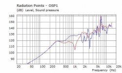
In akabak3 I put two BEM shell componests set as radiating discs in the same location in one 'exterior' subdomain. One is rotated 180 degrees, has 'Weight =-1' and ' Direction = Normal to surface.
I think the attached results look broadly right.
In akabak3 I put two BEM shell componests set as radiating discs in the same location in one 'exterior' subdomain. One is rotated 180 degrees, has 'Weight =-1' and ' Direction = Normal to surface.
I think the attached results look broadly right.
Attachments
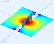
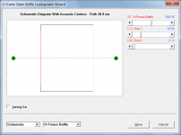
Next up I tried using the 'duct' component to make a U frame for the disc. I set the rotated disc (i.e. the rear surface) to point into the frame and put that in an 'internal' subdomain. Then added an 'interface' subdomain to link interior and exterior and put a flat transition plane (like a transparent baffle) across the back of the frame.
Again I think the polar looks OK. I'm not sure about the freq. responses. And I'm not confident that this is the correct approach.
I also need to work out how to use the LEM section and link it to BEM whilst keeping all the polarities right. I am sure it is worth perservering but the scope to get something wrong (at least for me) is very high.
I'd welcome any thoughts on whether this is vaguely the right way to start.
Attachments
Last edited:
LEM part is easy, not possible to make big errors here. You need to define speaker element with all his T/S parameters and 2 diaphragms, font and rear and bind then to BEM diaphragms. Look sample projects.
Probably you had same problem as I: thin-shape breakdown effect caused by too close BEM elements. Explanation from internet: "...when it is used in modeling acoustic wave problems in domains (either interior or exterior) containing thin shapes, the two equations from both sides of the thin shape are identical in the limit as the thickness approaches to zero."
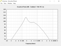
I made calculation of close baffle with Hornersp as in your dipole project and get dipole peak at about 670 Hz.
Probably you had same problem as I: thin-shape breakdown effect caused by too close BEM elements. Explanation from internet: "...when it is used in modeling acoustic wave problems in domains (either interior or exterior) containing thin shapes, the two equations from both sides of the thin shape are identical in the limit as the thickness approaches to zero."
I made calculation of close baffle with Hornersp as in your dipole project and get dipole peak at about 670 Hz.
Last edited:
U-frame with similar dimensions give in Hornresp dipole peak at 300Hz.
Actually much better results than with my way of AKABAK using.
But I had also only one subdomain, no interface. I need to try to repeat your approach. This must be way to avoid thin-shape breakdown effect.
Actually much better results than with my way of AKABAK using.
But I had also only one subdomain, no interface. I need to try to repeat your approach. This must be way to avoid thin-shape breakdown effect.
Last edited:
Actually much better results than with my way of AKABAK using.
Not sure if it helps to explain the reason for the differences, but Hornresp calculates the positions of the point source acoustic centres, and uses them in the simulation model.
Attachments
Beyma 15P80FE IB simulation
I am attempting to learn AKABAK so as an exercise I have attempted to replicate the datasheet measurement of the Beyma 15P80FE found in its datasheet:
https://www.beyma.com/speakers/Fichas_Tecnicas/15P80Fe.pdf
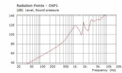
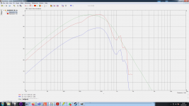
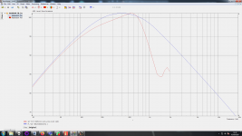
this is a smooth extended response ~ 100dB/1W 120Hz -l 1.5kHz whereupon the response looks to be further extended by breakup until 4kHz. I have simulated the 1m 2.83Vrms response in both HornResp (green) and akabak3 (red = 1m) blue = 2m. Both use 1000L enclosure volume. As far as I am aware the response in Hornresp should match Akabak until the cone starts to beam however the Akabak response looks to be 3dB down and isn't anymore extended than Hornresp.
The Akabak simulation is a coupled LEM, BEM simulation using an infinite baffle and two calculation domains with a shell over the driver to provide an interface like the example "IB-Cone-3D with Elements.akp" and the model used for the driver inductance in both cases is the simplest non complex inductance model. I turned the number of mesh elements very high and ran the simulation for a few hours but it didn't make a difference to the results.
I am attempting to learn AKABAK so as an exercise I have attempted to replicate the datasheet measurement of the Beyma 15P80FE found in its datasheet:
https://www.beyma.com/speakers/Fichas_Tecnicas/15P80Fe.pdf
this is a smooth extended response ~ 100dB/1W 120Hz -l 1.5kHz whereupon the response looks to be further extended by breakup until 4kHz. I have simulated the 1m 2.83Vrms response in both HornResp (green) and akabak3 (red = 1m) blue = 2m. Both use 1000L enclosure volume. As far as I am aware the response in Hornresp should match Akabak until the cone starts to beam however the Akabak response looks to be 3dB down and isn't anymore extended than Hornresp.
The Akabak simulation is a coupled LEM, BEM simulation using an infinite baffle and two calculation domains with a shell over the driver to provide an interface like the example "IB-Cone-3D with Elements.akp" and the model used for the driver inductance in both cases is the simplest non complex inductance model. I turned the number of mesh elements very high and ran the simulation for a few hours but it didn't make a difference to the results.
Attachments
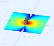
I think I might have worked it out one error the interface was the wrong way round and should have been: exterior (sub domain 1), cone (sub domain 2). This way round has much cleaner results and now Hornresp and Akabak are within 1dB at 100Hz (which could be differences in the T/S parameters as it wasn't posible to get them identical in both software - presumably because the datasheet isn't accurate and different parameters are regarded as fundamental). However in both Hornresp and Akabak I'm still seeing the level falling beyond 600Hz while in the datasheet this is not happening till 4kHx so some effect is missing from the simulation.
However in both Hornresp and Akabak I'm still seeing the level falling beyond 600Hz while in the datasheet this is not happening till 4kHx so some effect is missing from the simulation.
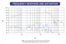
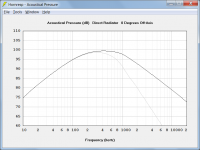
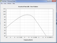
Hornresp models the driver diaphragm as a rigid plane circular piston. The Beyma diaphragm will not be rigid at 4000 Hz. The grey trace in the attachment shows the Hornresp power response for the driver mounted in an infinite baffle. The black trace shows the on-axis pressure response.
Attachments
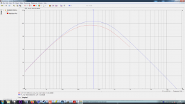
Thanks for the tip, I have now overlayed the onaxis frequency response rather than the power response from Hornresp (blue). To align the low frequency response better I should measure the T/S parameters of the driver myself to have totally consistent parameters so they can be the same in both software. The next thing I will try though is to replace the diaphragm model with a flat disk as per Hornresp in an attempt to get the HF response to better match.
I have found that there is no need to use the built in baffle on the diaphragm component if using an IB wall in the plane of the driver (as you would expect) so I have turned that off.
I have found that there is no need to use the built in baffle on the diaphragm component if using an IB wall in the plane of the driver (as you would expect) so I have turned that off.
Attachments
I corrected the T/S parameters so that they are as close to identical as I could make them in Hornresp and Akabak, turns out that the beyma datasheet is consistent I just needed to pay more attention in my data entry. I have also switched the Akabak simulation to using a flat disk instead of the diaphragm model. Results are now very close with LF identical and about 1.5dB less output in Akabak compared to Hornresp in the HF
Attachments

- Home
- Design & Build
- Software Tools
- AKABAK 3