UPD: Version available
Download SA01 Spectrum Analyzer — XDXD Solutions
Hi all! I'm in the middle of development of a spectrum analyzer software, and would like to share my insights as well as hear your ideas about it")
Yes, it will cost money. Circa $50 for community and $300 for professional editions, without any difference whatsoever between the versions (Pro is for >~10 employees company). I'm unemployed for the past year and working full-time on this project.
If i've misplaced the thread, please move it to the "vendors" section. The software is still in development and i don't have any due date...
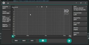
This is how it looks right now:
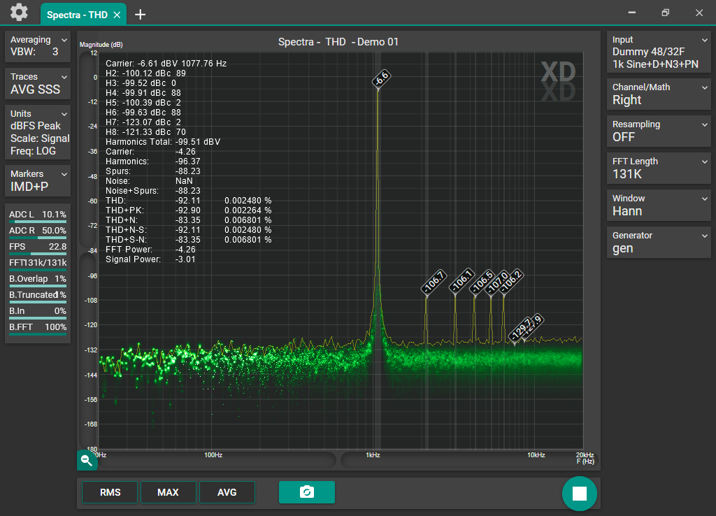
I'm trying to cover all the useful audio measurement techniques as well as implement more generic processings - to give some freedom to the end user regarding the workflow. Works with sound cards (WASAPI/ASIO/MME). Might support other hardware in future. Windows only I'm already too deep in windows/hardware optimizations/quirks, can't make them cross-platform.
It's about being a tool rather than "following strict orders", mimicking hardware-based analyzers.
Touch, eyes and user-friendly, without much handicapping nor over-complicated settings, everything is within reach of 2 clicks to modify and ZERO CLICKS to see
So far i've got it running
- 16M FFTs at 11FPS (i7 4790k), or like 0.5-1FPS on really weak Atom tablet. 20-25FPS 65K FFT on the same tablet.
- Phosphor/persistence display + display of "all FFT points"
- Various math and averaging options, including synchronous averaging that actually works without sync signal (20dB noise reduction in couple of seconds), cross-correlation, 2-channel transfer functions and so on
- "Very-Dynamic-Sample Rate Converter" - both for the basic stuff (SRC, decimation) as well as neat PLL-locking to measured signal's carrier frequency and reducing it's phase noise/wander, as well as syncing it to "bin centre" frequency for window-less scalloping-less or consistent really-long-FFT measurements.
- Phase Noise measurement
- Support of "notch/filtered" THD, IMD measurements by performing 2-channel FFT and then combining responses together (most consistent way of doing such thing)
- "Noise floor extension"
and many more
Currently i'm working on implementing on-the-fly switchable measurement setups in "chrome tabs" way. It's quite possible you won't have to stop the measurement flow whilst switching between tabs... quite a challenge as i need to switch ALL of the measurement settings altogether without any hiccup.
More on Software Spectrum Analyzer — XDXD Solutions
Download SA01 Spectrum Analyzer — XDXD Solutions
Hi all! I'm in the middle of development of a spectrum analyzer software, and would like to share my insights as well as hear your ideas about it
Yes, it will cost money. Circa $50 for community and $300 for professional editions, without any difference whatsoever between the versions (Pro is for >~10 employees company). I'm unemployed for the past year and working full-time on this project.
If i've misplaced the thread, please move it to the "vendors" section. The software is still in development and i don't have any due date...
This is how it looks right now:
I'm trying to cover all the useful audio measurement techniques as well as implement more generic processings - to give some freedom to the end user regarding the workflow. Works with sound cards (WASAPI/ASIO/MME). Might support other hardware in future. Windows only
I'm already too deep in windows/hardware optimizations/quirks, can't make them cross-platform.It's about being a tool rather than "following strict orders", mimicking hardware-based analyzers.
Touch, eyes and user-friendly, without much handicapping nor over-complicated settings, everything is within reach of 2 clicks to modify and ZERO CLICKS to see
So far i've got it running
- 16M FFTs at 11FPS (i7 4790k), or like 0.5-1FPS on really weak Atom tablet. 20-25FPS 65K FFT on the same tablet.
- Phosphor/persistence display + display of "all FFT points"
- Various math and averaging options, including synchronous averaging that actually works without sync signal (20dB noise reduction in couple of seconds), cross-correlation, 2-channel transfer functions and so on
- "Very-Dynamic-Sample Rate Converter" - both for the basic stuff (SRC, decimation) as well as neat PLL-locking to measured signal's carrier frequency and reducing it's phase noise/wander, as well as syncing it to "bin centre" frequency for window-less scalloping-less or consistent really-long-FFT measurements.
- Phase Noise measurement
- Support of "notch/filtered" THD, IMD measurements by performing 2-channel FFT and then combining responses together (most consistent way of doing such thing)
- "Noise floor extension"
and many more
Currently i'm working on implementing on-the-fly switchable measurement setups in "chrome tabs" way. It's quite possible you won't have to stop the measurement flow whilst switching between tabs... quite a challenge as i need to switch ALL of the measurement settings altogether without any hiccup.
More on Software Spectrum Analyzer — XDXD Solutions
Attachments
Last edited:
An interesting feature i've added lately: Phase-Locking of sampling process to measured signal.
The problem: When measuring analog signal generators (as Victor's and others), they tend to drift a little. Very-very little, but enough to ruin long (1M+ samples) FFTs - as the signal drifts, it's level spreads across several FFT bins during the measurement, and as a result, the measured level averages between them ( = drops).
The typical solution is to synchronize the generator to some frequency standard (or sampling clock of the sound card). But... another way is... synchronizing the ADC to the measured signal! Which is not feasible, as it requires hardware CLK input on the sound card, frequency multiplier/divider and VCO... Complicated.
Unless you do it in software.
Typical sample rate converters are DAC-ADC chain in essence. "DAC" converts the digital signal into some more-or-less analog one by upsampling and low-passing by brickwall filter. And the ADC part captures the samples at it's own time positions and frequency.
My implementation uses x32 upsampler:
SSSSSS - Input signal
000S000S000S000S000 - Zero stuffing (x4 upsampler for simplification)
0129210000000000000 - Convolution by Sinc-filter (0129210)
0000012921000000000
0000000001292100000
0000000000000129210
----------------------------
*+
0129222922292229210
The "Sinc" filter is obtained by Sin(X)/X function, which is truncated by Kaiser-9 windowing function (can't use sinc as-is as it has infinite length) (Kaiser is choosen for it's good suppression of tails of Sinc function as well as overall smoothness).
The upsampled signal is then sampled by "ADC" dT intervals (where dT equals 1/Fs of target sample rate). The sampling itself is performed by quadratic interpolation between 3 upsampled points taken at position of dT. Quadratic interpolation worked better than the rest i've tried (linear - correct physics but imprecise, cubic - incorrect physics and has discontinuities of slope in points of connection between samples).
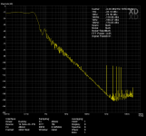
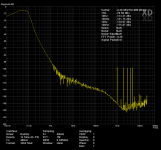
The magic happens when i take carrier embedded in the incoming signal, compute the time period of the carrier (by zero-crossing detector with interpolations, oversampling and filtering), compute the difference against constant frequency, and feed the delta to... "dT" parameter of the ASRC, every sample!
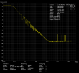
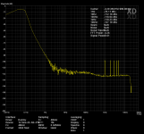
The result is... the wandering "990Hz" turns into stable "1000Hz"
Attached are screenshots of synthetic testbench, with and without "PLL", for both clean and noisy signal.
The problem: When measuring analog signal generators (as Victor's and others), they tend to drift a little. Very-very little, but enough to ruin long (1M+ samples) FFTs - as the signal drifts, it's level spreads across several FFT bins during the measurement, and as a result, the measured level averages between them ( = drops).
The typical solution is to synchronize the generator to some frequency standard (or sampling clock of the sound card). But... another way is... synchronizing the ADC to the measured signal! Which is not feasible, as it requires hardware CLK input on the sound card, frequency multiplier/divider and VCO... Complicated.
Unless you do it in software.
Typical sample rate converters are DAC-ADC chain in essence. "DAC" converts the digital signal into some more-or-less analog one by upsampling and low-passing by brickwall filter. And the ADC part captures the samples at it's own time positions and frequency.
My implementation uses x32 upsampler:
SSSSSS - Input signal
000S000S000S000S000 - Zero stuffing (x4 upsampler for simplification)
0129210000000000000 - Convolution by Sinc-filter (0129210)
0000012921000000000
0000000001292100000
0000000000000129210
----------------------------
*+
0129222922292229210
The "Sinc" filter is obtained by Sin(X)/X function, which is truncated by Kaiser-9 windowing function (can't use sinc as-is as it has infinite length) (Kaiser is choosen for it's good suppression of tails of Sinc function as well as overall smoothness).
The upsampled signal is then sampled by "ADC" dT intervals (where dT equals 1/Fs of target sample rate). The sampling itself is performed by quadratic interpolation between 3 upsampled points taken at position of dT. Quadratic interpolation worked better than the rest i've tried (linear - correct physics but imprecise, cubic - incorrect physics and has discontinuities of slope in points of connection between samples).
The magic happens when i take carrier embedded in the incoming signal, compute the time period of the carrier (by zero-crossing detector with interpolations, oversampling and filtering), compute the difference against constant frequency, and feed the delta to... "dT" parameter of the ASRC, every sample!
The result is... the wandering "990Hz" turns into stable "1000Hz"
Attached are screenshots of synthetic testbench, with and without "PLL", for both clean and noisy signal.
Attachments
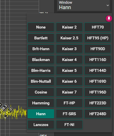
The usual way to deal with spectral leakage is use a flattop window so you can accurately measure peak height. For high end audio you need a good flattop window with a large dynamic range. This is a great resource for such windows: https://holometer.fnal.gov/GH_FFT.pdf
Yeah, very-very nice paper, i've implemented most of them (excluding the SFT3 family).
Maybe is should drop some HFTs in favor of addition of SFT3s:
Another great paper is
Exact Signal Measurements using FFT Analysis - Stefan Scholl
https://kluedo.ub.uni-kl.de/frontdoor/deliver/index/docId/4293/file/exact_fft_measurements.pdf
It describes all of the FFT's issues.
Using flattop windows reduce/eliminates the scalloping loss (peak level reduction of frequency component, which falls between exact bin frequencies, for example max error of Hann window is -1.4dB).
Spectral leakage is a result of discontinuities at the edges of FFT buffer. Window function's shape on the edges is the one that is responsible on "noisiness" of spectra around the carrier (you get slight "flashes" as if you had no window applied).
The thickness of carrier gets affected too, but is quite consistent and mostly lacks importance at high FFT lengths and typical views/measurements.
The thickness of carrier gets it's importance in phase noise view, where you want to look at the shape of the carrier, at very close offsets from the peak. Flattop windows result in quite a wide peak, which might cover/affect actual close-in phase noise. I haven't found any solution that felt "in line" with my "feelings" (covering _all_ of the window shapes, not just Hann or "rectangular" general case, and computationally efficient/straightforward), so i've implemented my own (currently untested, but i don't see where it might fail - it's quite bulletproof).
-----------
Scalloping = level error of peaks
Spectral leakage = "noise around"/thickness of carrier.
Attachments
Last edited:
Looks very good, are you planning on adding a generator with thing like chirps for speaker measurement and mic eq file?
Lukas
Generator will be there, with all the tones/features i could imagine
Same for compensations, the moment i'll implement trace storage/manager. I already have the generator section ready, including FFT synthesis, signal modifiers and everything, but it lacks UI.But... acoustical measurements are very different subject, and i don't think this software suits them by design/concept... Acoustical measurements are "single shot" or "repetitive-averaged" - for impulse response/echo/room gating, whilst this software is for continuous monitoring and displaying...
I might look for acoustical stuff a bit later, as i already have a code suite that deals with impulses, gating, transforms e.t.c..
I'd personally go for HOLMImpulse for acoustic stuff, it's really great and complete solution.
Thanks!I like it!

I hope to push public beta in 10 days, fingers crossedWhen are you going to make it public
Really nice looking package. Let us all know when you have something to play with.
Suggestion- add ability to compensate for an external notch filter so not limited to the performance of an ADC.
Multitone tests? I use spectral contamination as a way to find difficult nonlinearities. I can share tables of numbers that don't have common harmonic or IM products.
Suggestion- add ability to compensate for an external notch filter so not limited to the performance of an ADC.
Multitone tests? I use spectral contamination as a way to find difficult nonlinearities. I can share tables of numbers that don't have common harmonic or IM products.
Ah excellent, thanks for recommending it.Another great paper is
Exact Signal Measurements using FFT Analysis - Stefan Scholl
https://kluedo.ub.uni-kl.de/frontdoor/deliver/index/docId/4293/file/exact_fft_measurements.pdf
It describes all of the FFT's issues.
For phase noise can you not just subtract the carrier out completely from the data? Its possible to estimate the carrier frequency and phase directly without the FFT given a close starting point by simple correlation techniques, limited only by the accuracy of the data - you are fitting a sine-wave to the data for least-squares error. Then you are not limited by bins or windowing,The thickness of carrier gets it's importance in phase noise view, where you want to look at the shape of the carrier, at very close offsets from the peak. Flattop windows result in quite a wide peak, which might cover/affect actual close-in phase noise. I haven't found any solution that felt "in line" with my "feelings" (covering _all_ of the window shapes, not just Hann or "rectangular" general case, and computationally efficient/straightforward), so i've implemented my own (currently untested, but i don't see where it might fail - it's quite bulletproof).
If you've not looked at it - you could use GPU FFT. The downside is the differences between nVidia, AMD and with Apple giving up OpenCL.. also PC and Mac.
GPUs can deliver extremely fast parallel computation.
In the image processing I used to upload 24MB images as a texture, then use the GPU to align and process the images using FFT phase correlation. The beauty of this technique is then you can render directly to the OpenGL window without having to retrieve through the slow PCI bus.
If data is needed to be retrieved, then you can process in the GPU and then simply download the results from the GPU to main memory.
With IEEE double precision being offered by nVidia and AMD and over 4GB of graphics ram available (although shared with applications, so not all available).
I ran at 17fps, the GPU was idling, however the astro CDD camera could only download the picture at 17fps!
Hi all!
I've compiled a x86 preview version, works till end of 2020
Download SA01 Spectrum Analyzer — XDXD Solutions
multi-tone distortion shouldn't make sense for now.
lacking generator feature.
lacking presets (just 3 for now) (they are just preconfigured settings for convenience, everything is available manually thru UI)
8M-16M FFTs might crash (memory limitation of x86 build)
Most of the features should work tested on W7 32/64, W8 64, W10 64.
Requires .NET 4.6.1 and Intel MKL (available for download at app download page).
If it crashes, please upload the crash.txt from the My Documents folder. If you get something weird, please upload screenshot.
I'm unsure if any features will work when acquisition is stopped. If you switch settings during runtime, you should be ok.
Thanks for your time and hope it works
I've compiled a x86 preview version, works till end of 2020
Download SA01 Spectrum Analyzer — XDXD Solutions
multi-tone distortion shouldn't make sense for now.
lacking generator feature.
lacking presets (just 3 for now) (they are just preconfigured settings for convenience, everything is available manually thru UI)
8M-16M FFTs might crash (memory limitation of x86 build)
Most of the features should work
tested on W7 32/64, W8 64, W10 64.Requires .NET 4.6.1 and Intel MKL (available for download at app download page).
If it crashes, please upload the crash.txt from the My Documents folder. If you get something weird, please upload screenshot.
I'm unsure if any features will work when acquisition is stopped. If you switch settings during runtime, you should be ok.
Thanks for your time and hope it works
Last edited:
Fixed the bug, available at
Download SA01 Spectrum Analyzer — XDXD Solutions
No need to uninstall previous versions.
Download SA01 Spectrum Analyzer — XDXD Solutions
No need to uninstall previous versions.
Working on signal gen side of things.
Got some pseudo-language for describing the signal a-la
which translates into 2 sine waves at 10, 11kHz at -6dB level each + noise at -100dB, distorted and then put into left and right channel with additional -90dB noise at each channel.
or
Which translates into sum of sines at 50, 70, 500, 700Hz and -100dB each + white noise at -100dB put as phase noise of sine at 1kHz -10dB.
Then this signal is added to white noise (same for L and R channels) + another white noise for each channel.
I'm doing this for internal "dummy" generator to validate different measurement schemes.
But it seems it has place on the input preprocessing too (application of filters, dithering ADC rounding errors etc).
Might come handy as separate application a-la "Signalpad" where you type-in your signal scheme and get the output in real time.
a-la
Huh.
Whatever, it's cool.
Got some pseudo-language for describing the signal a-la
Code:
var noise_src = new WhiteNoise(-100);
var noise_adc_l = new WhiteNoise(-90);
var noise_adc_r = new WhiteNoise(-90);
var s1 = new Sine(Fs, 10000, -6);
var s2 = new Sine(Fs, 11000, -6);

var src = new Distortion((noise_src + s1 + s2), 0.001, 0.001, 0.001, 0.001, 0.001);
out_l = src + noise_adc_l;
out_r = src + noise_adc_r;
which translates into 2 sine waves at 10, 11kHz at -6dB level each + noise at -100dB, distorted and then put into left and right channel with additional -90dB noise at each channel.
or
Code:
var noise_src = new WhiteNoise(-100);
var noise_adc_l = new WhiteNoise(-90);
var noise_adc_r = new WhiteNoise(-90);

var s_pn1 = new Sine(Fs, 50, -100);
var s_pn2 = new Sine(Fs, 70, -100);
var s_pn3 = new Sine(Fs, 500, -100);
var s_pn4 = new Sine(Fs, 700, -100);
var s_pn_noise = new WhiteNoise(-120);
var tot_phase_noise = (s_pn1 + s_pn2 + s_pn3 + s_pn4 + s_pn_noise);

var s1 = new Sine(Fs, 1000, -10, tot_phase_noise);

out_l = s1 + noise_src + noise_adc_l;
out_r = s1 + noise_src + noise_adc_r;Then this signal is added to white noise (same for L and R channels) + another white noise for each channel.
I'm doing this for internal "dummy" generator to validate different measurement schemes.
But it seems it has place on the input preprocessing too (application of filters, dithering ADC rounding errors etc).
Might come handy as separate application a-la "Signalpad" where you type-in your signal scheme and get the output in real time.
a-la
Code:
out = (in.Notch(1000) + Noise(-100)).Gain(30) + Sine(1100, -100);Whatever, it's cool.
- Status
- This old topic is closed. If you want to reopen this topic, contact a moderator using the "Report Post" button.
- Home
- Design & Build
- Software Tools
- SA01 Spectrum Analyzer software - development in progess...