I have used Eagle when creating PCB, and LTSpice for modelling, but have yet to find a good piece of software for drawing pretty circuits.
Both Eagle and LT Spice will get you a circuit, but I dare anyone to call them good looking.
So please, is there anyone here who can help me find a nice piece of software that'll help me draw pretty circuits that I can share with others?
Here is a wish list for features that would be great if they are available.
1. Tube symbols.
2. Transformers with multiple taps.
3. Little arches shown where traces pass without connecting. (I think it's considered old American way of drawing?)
4. The ability to draw diagonal lines/connections.
5. Rotate and flip components (maybe even in 45° steps).
(6. Gold star if it's freeware)
Those are the features I've never been able to find in one piece of software.
How hard can it be? We're not talking simulations/modelling, or PCB/routing, etc. I'm just looking for some way to create pretty tube circuits.
Tube CAD Journal has beautiful circuits...
Any ideas?
You can take a look at KiCAD. It's free and contains a section "Valves" with 15-20 tube symbols. I'm not sure how man transformers are available but in any case you can easily create your own symbols.
And, yes - it has an potion for displaying non connected crossing wires like "arcs".
And, yes - it has an potion for displaying non connected crossing wires like "arcs".
When I use to write electronic documentation, we used Visio which is a Msoft product that integrates with Word. I know that Bob Cordell uses Visio for his books. It is a bit cumbersome to use but does make pretty pictures.
No gold star, you have to pay.
I see there are some clones out there, try them out.
No gold star, you have to pay.
I see there are some clones out there, try them out.
Last edited:
When I used to write electronic documentation, we used Visio which is a Msoft product that integrates with Word. I know that Bob Cordell uses Visio for his books. It is a bit cumbersome to use but does make pretty pictures.
No gold star, you have to pay.
I see there are some clones out there, try them out.
You might find some "bargins" on Ebay, cheap enough to try.

There's an online tool from Digikey, Scheme-it, which does pretty well.
Scheme-it | Free Online Schematic and Diagramming Tool | DigiKey Electronics
Scheme-it | Free Online Schematic and Diagramming Tool | DigiKey Electronics
Altium Designer is as far as I know, the "nicest" software, fairly complex and I need to learn it properly. Then there is EasyEDA which I am going to try myself.
EasyEDA - Online PCB design & circuit simulator
EasyEDA - Online PCB design & circuit simulator
Thx ahankinson,
I never paid attention to it, thinking they are gimmicks.
A minute or two playing around with Scheme-it and I like it.
I see it will export to KiCad and doc formats, png, pdf.
It will rubber band a net ( they call it a link) and move it with a comp. iirc Visio does not do that, at least the version I was using.
That is cool we have a Kicad developer in the crowd.
Catalog assign for a symbol like a jfet, could go directly to that part type in the Digi-key database.
I have heard good things about KiCad, I would have to investigate its capabilities.
Last edited:
Ha! I never thought I'd see those two together in the same thread. I was the chief architect of FrameMaker back in the 90s; now retired I contribute to Kicad.
We still have a professor using Framemaker for writing technical books
because of all the equations, since the 90s. He won't use anything else.
He's over 80.
Last edited:
Tinycad is functional (and free), but may not be pretty enough for you.
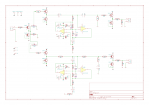
Kikad schematics are not bad. Attached is an example from an old version, not sure how much it has changed... I think they have a fairly extensive component library these days.
Tony.
Kikad schematics are not bad. Attached is an example from an old version, not sure how much it has changed... I think they have a fairly extensive component library these days.
Tony.
Attachments
I actually liked FrameMaker back in the day. And I found a tiny web app for drawing that actually worked pretty well, draw.io.
You have access to the components and can modify them freely using script language similar to canvas.
It takes a while to set up the components, but the end result is above par imho.
You have access to the components and can modify them freely using script language similar to canvas.
It takes a while to set up the components, but the end result is above par imho.
Xcircuit is great tool to create publication-quality circuit diagrams. I use it all the time. It may not be intuitive, but once you get the hang of it, it's super efficient.
There are many add-on libraries for part symbols, and it's also easy to create your own symbols. For instance, I also use it for my real job where I sometimes need to draw diagrams of vacuum systems with like pumps, getters, gas traps, mass specs, etc.
Note that the on-screen display of the xcircuit editor is optimized for the editing task. The graphics quality of the output file (postscript) is on an entirely different quality level. You can always convert the drawing postscript to a PDF or pretty pixel graphics file using some conversion tool (ps to pdf, ps to PNG or ps to JPG etc.)
The xcircuit website does not look pretty to my eyes, but it is very informative.
This post has an example of a schematic I did with xcircuit. If there's something you don't like about the graphics in there, it was most likely my fault, not xcircuit.
Last edited:
- Status
- This old topic is closed. If you want to reopen this topic, contact a moderator using the "Report Post" button.
- Home
- Design & Build
- Software Tools
- Help find software for drawing pretty circuit diagrams