Hello!
I'm looking for help with my current build project. I've been using VirtuixCAD to model a custom crossover to replace the Dayton Audio pre-assembled one I've been using for a few years in my 3-Way speakers.
After assembling the crossover and installing it, I noticed that the mid driver's response just doesn't sound right. To me it sounds very flattened and neutered compared to what I'm used to. Voices, piano melodies, guitars, etc, don't seem to have the punch that they should, like there's a "hole" in the sound.
As this is my first time assembling my own crossover, I'm certain I've made more than a few mistakes this first time around, however I'm looking for help in order to determine what I might have did wrong and if my project is salvageable.
One thing that's a bit of a mystery to me is that I'm unsure what the "ideal" phase graph should look like for a 3-way system. I'm sure this is very 101 type stuff, especially for this forum, but any help would be appreciated as I've been working very hard on this for the last couple of weeks and would like to see this project come to a close in a satisfying way. I'm currently stuck with the old pre-built crossovers in the cabs because the ones that I've made simply don't sound right
Please let me know if there's any other information I need to share for this post to be helpful and thank you for your time.
Last edited by a moderator:
 Like this:
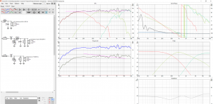
Well there's your problem... you have no phase data to start a crossover from. In simple and inaccurate terms, you have a "time of flight" that is different between speakers and that results in a phase offset that is not in the SPL traces. This difference is related to the positions of the voice cois relative to their position on a baffle.
Try a +30mm Z position offset for the midrange, and +80 for the bass, and see what happens.
What kind of microphone do you have?
Try a +30mm Z position offset for the midrange, and +80 for the bass, and see what happens.
What kind of microphone do you have?
So I was careful to make sure that the mid was hooked up so it sits inverted within the circuit. Even still this issue persists. The lows and highs sound fantastic but the mids are severely flattened.Do you have all your drivers hooked up with the positive terminal going to the same side of the crossover? Your schematic appears to be second-order, and typically we run those with the midrange hooked up "backwards". Try that.
I have an AKG D5. Also now that I'm looking at the explanation you sent regarding Time-Alignment, I'm not 100% sure if phase is my issue here or not. While it's very likely that there are some summing issues with my current set-up (as it's something I didn't factor in during the initial build), would it not be true that if I isolated the mid that I would hear the fuller frequency output that I would be expecting?Well there's your problem... you have no phase data to start a crossover from. In simple and inaccurate terms, you have a "time of flight" that is different between speakers and that results in a phase offset that is not in the SPL traces. This difference is related to the positions of the voice cois relative to their position on a baffle.
Try a +30mm Z position offset for the midrange, and +80 for the bass, and see what happens.
What kind of microphone do you have?
I'm sure phase is one of the issues here. Also, did you include baffle diffraction effects in your simulation?
Measurement mics are omnidirectional. Maybe someone else might know if your mic (supercardiodid as I found?) may be of use. It's not a calibrated omni measurement mic but better than nothing at all.
Measurement mics are omnidirectional. Maybe someone else might know if your mic (supercardiodid as I found?) may be of use. It's not a calibrated omni measurement mic but better than nothing at all.
I have not! I'll take some time today to learn how to put that into the software and get back to you. Thankfully the cabinets and driver positions are fixed so it shouldn't be too tough to do.I'm sure phase is one of the issues here. Also, did you include baffle diffraction effects in your simulation?
Measurement mics are omnidirectional. Maybe someone else might know if your mic (supercardiodid as I found?) may be of use. It's not a calibrated omni measurement mic but better than nothing at all.
"The question is whether we can make a crossover at all without measurements - and the answer is NO.
It cannot be done, and crossovers cannot be calculated.
We cannot use manufacturers' data sheets to simulate crossovers either, although I know some dealers do so. The frequency response data are most often taken from an "infinite" baffle that does not in any way resemble your cabinet. These data do not contain proper phase data, etc. We also need to measure the actual acoustic distance to drivers from an assumed listening point to get proper phase integration. This simply cannot me calculated, only careful measurements can tell."
(The above was taken from Crossovers and it is the ugly truth)
Simulation and hearing can only get you so far.
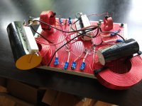
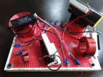
Glad that you asked about the crossover construction! That's where my mind was going next as well, as this is the first time I've ever made one. Apologies if the messiness gives you nightmares, but I did the best I could!
Let me know if there are any super obvious things I did that might affect the output.
Let me know if there are any super obvious things I did that might affect the output.
Attachments
I looked hard but didn't find anything. A bit difficult to do here. I guess you have the midrange inverted as in your simulation? (That would be normal in a 3-way with 2nd order slopes). The high xo slopes look more like a (messy!) 3rd order acoustically.
Did you run the midrange alone? What do you think, is the low or high xo point a problem, or both?
Enough clearance between connections, also when installed? No loose parts?
Did you use measured or calculated impedance data for the simulation? I hope you did not asdume flat resistance.
Other things, but probably unrelated:
Resistors may get hot when playing levels are high. I would generally avoid putting them on other parts, caps especially.
High xo is very high for such combination. Usual would be 2.5-3.5 kHz with the drivers used here.
So I did test the mid-range yesterday by themselves (switching between the inverted custom crossover and the pre-built Dayton Audio) and they still sound bizarrely muddled. When I change it so that the mid-range is NOT inverted, I get a better sound out of the mid, but then that polarity switch diminishes the quality of the woofer and tweeter (even when I then invert those).
Is there a chance that the high xo point might be severely diminishing the quality of the output of the mid? I want to believe this because it's very fixable, but at the same time the pre-built crossover advertises a 700/5.5k xo points, so I'm not sure what to make of that.
The impedance values were supplied via the manufacturer for all drivers EXCEPT the woofer. I don't think I was able to find specs on that via Goldwood's site unfortunately, so that could be a major problem.
I looked hard but didn't find anything. A bit difficult to do here. I guess you have the midrange inverted as in your simulation? (That would be normal in a 3-way with 2nd order slopes). The high xo slopes look more like a (messy!) 3rd order acoustically.
High xo is very high for such combination. Usual would be 2.5-3.5 kHz with the drivers used here.
Additionally, do you have a good example of what a smoother, less messy xo point would look like in the instance that I rebuilt or tweak the circuit in the future? Just so I know what to aim for?
What is that pre-built crossover anyway? A generic one?
Dayton Audio XO3W-700/5.6K 3-Way Speaker Crossover 700/5,600 Hz
- Status
- This old topic is closed. If you want to reopen this topic, contact a moderator using the "Report Post" button.
- Home
- Design & Build
- Software Tools
- Ideal 3-Way Speaker Phase