Victor's oscillator in a box
I posted this over in the Low-Distortion Audio-range Oscillator thread but thought it might be of interest to people here as well:
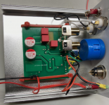
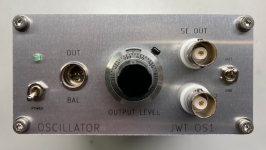
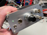
I decided to build a slightly more professional-looking enclosure for Victor's oscillator. Better shielding and improved connectors were the main goals. Similar to my stepped attenuator, I put it into a small 50x100x100 mm aluminum case. I designed the panel in KiCad and had it fabbed in aluminum by JLCPCB.
I replaced the level control with a 10-turn pot and vernier dial. This helps get consistent levels across multiple distortion runs with REW because the existing pot was a tad touchy. The RCA jacks were replaced with BNC connectors. I made provisions for a future differential output, probably consisting of an OPA1656 on a small piece of perf board (I don't have anything to test yet that has differential inputs).
Power comes from an external battery box with 4x 9Volt batteries.
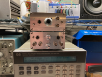
It is taking its place alongside some of my other test equipment.
Cheers
I posted this over in the Low-Distortion Audio-range Oscillator thread but thought it might be of interest to people here as well:
I decided to build a slightly more professional-looking enclosure for Victor's oscillator. Better shielding and improved connectors were the main goals. Similar to my stepped attenuator, I put it into a small 50x100x100 mm aluminum case. I designed the panel in KiCad and had it fabbed in aluminum by JLCPCB.
I replaced the level control with a 10-turn pot and vernier dial. This helps get consistent levels across multiple distortion runs with REW because the existing pot was a tad touchy. The RCA jacks were replaced with BNC connectors. I made provisions for a future differential output, probably consisting of an OPA1656 on a small piece of perf board (I don't have anything to test yet that has differential inputs).
Power comes from an external battery box with 4x 9Volt batteries.
It is taking its place alongside some of my other test equipment.
Cheers
Attachments
Has anyone used a USB isolator? Such as with an E-MU 0404 USB or similar? I am trying to find ways of getting rid of the last power line frequencies from the E-MU 0404 USB single ended loopback. (Such as ADUM3160 based.)
I guess another possibility would be to use a balanced to single ended converter mounted right on the input terminals of the tested power amplifier.
I guess another possibility would be to use a balanced to single ended converter mounted right on the input terminals of the tested power amplifier.
Last edited:
I've used an ADuM4160 based isolator board, which needs a battery supply to power the USB to EMU interface. It does suppress mains loop related hum artefacts, although not to the same level as a laptop obviously (which is what I use now if I need to mitigate those artefacts). I have noted a few ebay variations of the board over the years - using different voltage regulation circuitry. I had one ADuM4160 fail on me once, but it was fine once the chip was replaced.
With your E-MU 0404 USB and laptop do you still get mains related artifacts in your loopback test? Single ended loopback? I have some singled ended and I just wonder how much is to expected with the E-MU 0404 USB and laptop.
I also noticed that I get a little less mains related artifacts when testing my amplifier if my laptop is on AC power plugged into the same outlet as the power amplifier. It is a little higher when the laptop is on battery.
I also noticed that I get a little less mains related artifacts when testing my amplifier if my laptop is on AC power plugged into the same outlet as the power amplifier. It is a little higher when the laptop is on battery.
I only do single-ended measurements. If there are two devices powered from the mains then yes there are typically some artefacts showing - so given I normally use a PC at my bench then there are artefacts as the EMU is powered from the mains and typically so is the DUT.
I made up a battery feed for the EMU, which I use with a laptop, to then allow an item of mains powered equipment to be tested without any mains born hum/noise (unless it's radiated ingress). An advantage of other more modern USB soundcards is of course that they don't need a custom battery supply.
Single ended connections to an amp means I have to be careful to make the soundcard input and output gnds the same within the DUT.
However I am seeing the opposite which is odd. I am getting less artifacts when the laptop is on mains power plugged into the same outlet as the DUT. I get a little more artifacts on battery power. The E-MU is on battery power in both cases (power bank with 18650 inside).
It isn't enough to get very excited about but it seems odd.
It isn't enough to get very excited about but it seems odd.
I am using the balanced input along with the balanced attenuator for the measurements.
The input to the amplifier DUT is still single ended from the left output of the E-MU 0404 USB. The mains artifacts are still there and are very close to the same levels seen in the E-MU loopback test. So I am assuming that they are primarily coming from the single ended output of the E-MU 0404 USB.
The input to the amplifier DUT is still single ended from the left output of the E-MU 0404 USB. The mains artifacts are still there and are very close to the same levels seen in the E-MU loopback test. So I am assuming that they are primarily coming from the single ended output of the E-MU 0404 USB.
... I made provisions for a future differential output, probably consisting of an OPA1656 on a small piece of perf board (I don't have anything to test yet that has differential inputs).
See this: Low-distortion Audio-range Oscillator
You can have diff. output natively from the Victor's oscillator PCB.
Yes - I saw a post where somebody had taken a differential output from pin 7 of the dual opamp, but looking at the schematic of Victor's most recent version here, that while it is clearly 180 degrees out of phase with the main output, it is not at all clear to me why the amplitude would be identical and therefore not perfectly balanced.
Easy to test though - I'll check it out at some point.
Easy to test though - I'll check it out at some point.
It is not required for a balanced signal that the signal levels are the same with respect to ground. It really is irrelevant. The advantage of balanced lines is that, if you have the source- and receiving end impedances the same, any interference from outside is cancelled in the receiving end.
In fact, if you require both signals to be the same with respect to grounds, you re-introduce ground as a reference, which you wanted to avoid in the first place by going balanced.
There is also something called symmetrical signaling, but that has a completely different purpose and properties.
Jan
In fact, if you require both signals to be the same with respect to grounds, you re-introduce ground as a reference, which you wanted to avoid in the first place by going balanced.
There is also something called symmetrical signaling, but that has a completely different purpose and properties.
Jan
Quite true - it just upsets my ideas about symmetry. 
The main output passes through 2 200 Ohm resistors in parallel, so those would have to be bypassed (or 100 Ohms added to the pin 7 output - probably better) to have balanced output impedance.
In any event - I do not currently have any audio gear to test with differential inputs, so not a priority - too many other projects!
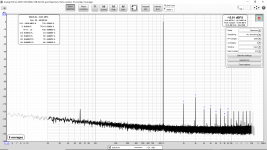
Attached is THD at 64W (4 Ohms) of L20.5 with modifications: Genuine Toshiba 2SC5171/2SA1930 drivers and with four output pairs of Toshiba (Japan) O gain rank 2SC5200 and 2SA1943.
By the way, does anyone know of a practical/safe modification to the E-MU 0404 (USB) to clean up the noise on the other channel?
By the way, does anyone know of a practical/safe modification to the E-MU 0404 (USB) to clean up the noise on the other channel?
Attachments
Last edited:
Thanks. That looks very good. At the very end of that thread someone mentions cleaning up the 6V supply with a low ESR solid polymer but did not provide any details or PCB photos. Did you ever mod the supplies inside the E-MU 0404 USB? If so, do you know of a good thread for that also?
kozard - you may be chasing a solution when there isn't a problem. All I can suggest is to make repeatable benchmark tests and make single modification steps, so as to adequately identify the character of any modification (and reduce the risk of causing some accidental outcome along the way). I'm loath to break open my 0404 until I 'have' to, which to me means using the quiet channel if I need to, but otherwise not being concerned about the noisy channel.
I understand your point. I have repaired a number of E-MU 1616m and 1820m microdocks and the quality and reliability of the electrolytic capacitors in them is poor. (The ADC/DAC and op-amps are good, as are the ultra low noise regulators that only the 1616/1820 have. The electrolytics are not good brands/quality/reliability, however.) Many that I have removed have extreme ESR and little to no capacitance at this age. The 0404 USB is likely quite a bit better with the same poor capacitors inside since it runs cooler. However I would like to open it up and at least replace the old electrolytics since there is a performance difference between the two units I have. (I just picked up another used one for not much.)
The differential pair re-route mod for channel A input does not seem too scary.
Putting in quality Panasonic electrolytics should not be an issue. The main question I have is related to the instability and reboot loop. Is that just from too large a cap or is it also from too low an ESR?
The differential pair re-route mod for channel A input does not seem too scary.
Putting in quality Panasonic electrolytics should not be an issue. The main question I have is related to the instability and reboot loop. Is that just from too large a cap or is it also from too low an ESR?
Having more than one USB 0404 certainly changes the risk assessment - I keep looking but no luck on that aspect for me.
Unfortunately capacitance and maybe ESR can change the design performance of a dc/dc switchmode. ESR changes a lot with temp, so to have a substantial change in stability due to say a 10:1 change in ESR seems a bit concerning. It would get arduous to assess why there was a high level stability or control change when a cap is changed, but at least you can swap it back or change it again to do some basic fact finding.
Unfortunately capacitance and maybe ESR can change the design performance of a dc/dc switchmode. ESR changes a lot with temp, so to have a substantial change in stability due to say a 10:1 change in ESR seems a bit concerning. It would get arduous to assess why there was a high level stability or control change when a cap is changed, but at least you can swap it back or change it again to do some basic fact finding.
- Home
- Design & Build
- Software Tools
- How to - Distortion Measurements with REW