I don't know the reason why yet but some equipment seems to be very easily measured with my desktop with the E-MU PCI card and 1820m/1616m microdocks. Examples include the ES9038Q2M and PCM1794 DACs. And those THD numbers are tiny compared with the uPC1342V power amplifier.
However the power amplifiers appear to be more difficult. Perhaps they are more sensitive. Perhaps the gain of the uPC1342V power amplifier and/or CMRR and/or PSRR play a role? Plus the (data) inputs of the DAC are isolated by transformer or optical. Plus both DACs have balanced output options, yet single ended they still measure far better than the power amps with the desktop measurement system.
Anyways I ordered a fairly low cost E-MU 0404 USB (used) and I will try that with the laptop. I will try the 1.40 beta drivers (W10, wish me luck). I can use the laptop on battery and I have 1/2/3/4 cell 18650 battery packs and linear 5V (LT1083) regulators that I can power the E-MU 0404 USB with.
I can also check the current capability of the 5V output on the Condor linear (LM723) supply that I have on my bench (+/-12V & 5V). Not sure what the actual current draw is for the E-MU 0404 USB.
That will likely be my last experiment in an attempt to get the best and most accurate uPC1342V measurements. If that fails I will simply continue on with the QUAD405-2 (with mods and OPA228) and the MX50X2 (with Toshiba outputs and drivers) which both are measuring better than the uPC1342V. I don't want to down select out the uPC1342V and L20 V7 but the MX50X2 and QUAD405-2 are winning so far.
I am also considering trying a linear regulated supply (NAIM) as another possible (future) experiment.
Last edited:
I think any desktop/deskside PC is going to be problematic as far as generating some noise goes. Just the nature of the beast, so putting a PCI soundcard inside that environment is bound to hamper efforts to get really low numbers. I have also seen notes from people about Raspberry Pis, especially the 4, as being noisy as well, both conducted and radiated noise. It's not just the CPU and the internal power supplies - it's everything connected like the monitor and keyboard.
I also see lots of FFTs posted with significant 50/60 Hz bumps (and other harmonics) due to noisy wall-wart power supplies, which I why I run my EMU 0404 on a 5V Lithium battery and float it and my laptop from what I am measuring. That seems to help lower the baseline.
One thing I have thought about is using a USB isolator. I am not sure if they have the bandwidth needed for USB soundcards, but might be a consideration in isolating the computer.
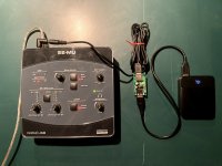
Well my E-MU 0404 USB arrived and I have attached balanced and single ended loop backs. I have noticed input B is a little better than input A. In case anyone is wondering if you search for 64-bit Windows 7 beta driver you can download version 1.40 beta driver from Creative and that installed and worked totally smoothly with latest Windows 10 64-bit.
The 0404 arrived with the original Creative 5V adapter so I have used that so far. The spectrum looks pretty nice, even single ended. I was thinking that 4xNiMH AA would be the right voltage and I have a 4xAA battery box. That should work without problems, right? (I have 2x18650 and LT1083 so I could also use that for 5V battery power.)
Next I will try remeasuring the uPC1342V amplifier with the E-MU 0404 and the balanced attenuator.
Attached (in order) is:
- Balanced right main output to TRS input B
- Single ended left main output to TRS input A
- Single ended left main output to TRS input B
Attachments
Last edited:
4 NiMH is 4 x 1.3 = 5.2V, nominally. Lots of sources quote NiMH as 1.2V like the old NiCd and this is not the case in my experience, freshly charged NiMH is likely to be upto 5.5V max, which should be compatible with most 5V logic devices.
However its probably worth checking, different manufacturers have different tweaks to the chemisty.
For 3.3V logic devices a single LiFePO4 cell is a good fit.
However its probably worth checking, different manufacturers have different tweaks to the chemisty.
For 3.3V logic devices a single LiFePO4 cell is a good fit.
kozard, my 0404USB draws 0.6 to 0.7A during operation at 5V. I use a dropper resistor and 7805 with cooling to allow it to be powered by a 12V SLA battery when needed. Not as convenient as USB powering for later devices but still practical when I need to avoid hum loop spikes.
One issue that can arise with soundcards is that the card likely connects its output and input grounds on the card - that is certainly the case with the 0404USB. That means that if the DUT has a noisy internal ground connection between its input and output terminals, then the measurement setup includes its own noise/hum loop. So checking what happens in the DUT with respect to grounding of input and output may be important.
One issue that can arise with soundcards is that the card likely connects its output and input grounds on the card - that is certainly the case with the 0404USB. That means that if the DUT has a noisy internal ground connection between its input and output terminals, then the measurement setup includes its own noise/hum loop. So checking what happens in the DUT with respect to grounding of input and output may be important.
I have wondered if some of the differences between amplifiers relates to the grounding and the layout related to the grounding.
I was wondering if I should try some of the common ground loop "fixes" to see if that has any influence. (Which might help point out what the issue is.) For example, why (in the same chassis with the same power supply and wiring) is it so easy to measure the QUAD405-2 and MX50X2? Why is the uPC1342V being more trouble-some? (And yes the measurements vary all over the place depending on where I move the load return and the measurement points.)
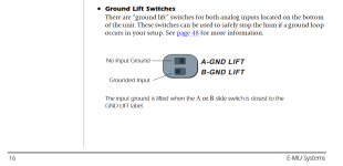
Do you use the ground lift switches on the bottom of the E-MU 0404 USB unit?
I was wondering if I should try some of the common ground loop "fixes" to see if that has any influence. (Which might help point out what the issue is.) For example, why (in the same chassis with the same power supply and wiring) is it so easy to measure the QUAD405-2 and MX50X2? Why is the uPC1342V being more trouble-some? (And yes the measurements vary all over the place depending on where I move the load return and the measurement points.)
Do you use the ground lift switches on the bottom of the E-MU 0404 USB unit?
Attachments
Last edited:
It's likely been more than a year or two since I've purposefully wanted to suppress any and all hum related signals - time flies -so I had to just check that I had the lift switches off. I'll double check their interaction next time I do an impedance test, and an external DUT test.
I use a scope probe as input connection, so can often clip the probe gnd to the input signal gnd within a DUT.
I use a scope probe as input connection, so can often clip the probe gnd to the input signal gnd within a DUT.
I have been using one of those lithium power packs intended for powering cell phones via USB. I got an adapter cable and plug to go from the USB output into the 5-volt input of the EMU (I think from Amazon). Seems to work fine and runs the EMU for several hours. No ground loops or mains hum. Since some of those battery units have buck/boost converters, I also use a small USB noise filter in between - it has a small common mode choke and some filter caps, but I am not sure it is even necessary.
Attachments
I have wondered if some of the differences between amplifiers relates to the grounding and the layout related to the grounding.
I was wondering if I should try some of the common ground loop "fixes" to see if that has any influence. (Which might help point out what the issue is.) For example, why (in the same chassis with the same power supply and wiring) is it so easy to measure the QUAD405-2 and MX50X2? Why is the uPC1342V being more trouble-some? (And yes the measurements vary all over the place depending on where I move the load return and the measurement points.)
Do you use the ground lift switches on the bottom of the E-MU 0404 USB unit?
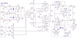
The ground lift switch only has an effect when you use the TRS receptacles. If you use the XLR input pins, the switch is out of the circuit. Also, the TRS jack connects to 5532 input buffers which add a small amount of distortion. The XLR input bypasses those buffers. Unfortunately, the XLR inputs also supply phantom power for microphones, which may affect some connected devices. Presumably, turning off the 48V power switch eliminates that as a concern. A possible mod might be to eliminate the resistor which feeds the phantom power to the jack. See attached schematic.
Attachments
I just built a linear PSU for my test gear.
Far more convenient than batteries, and no noise issues at all.
I used an LM350 regulator and this also powers my Raspberry Pi when I'm using that for audio measurements too.
I generally find that ground loops are the biggest issue with regards to noise.
I did a few test measurements to illustrate the ground issues when using USB especially.
One issue that can arise with soundcards is that the card likely connects its output and input grounds on the card - that is certainly the case with the 0404USB. That means that if the DUT has a noisy internal ground connection between its input and output terminals, then the measurement setup includes its own noise/hum loop.
You can use the balanced input as single ended, connecting the cold line to the DUT output ground.
phofman, in my particular setup I use a 100:1 scope probe that works well with the 1Meg unbalanced input of the 0404USB. Modifying that input scheme to present the probe across hot and cold lines would double the probe's load impedance to 2Meg (although that shouldn't have too adverse an effect).
I just built a linear PSU for my test gear.
Far more convenient than batteries, and no noise issues at all.
I used an LM350 regulator and this also powers my Raspberry Pi when I'm using that for audio measurements too.
I generally find that ground loops are the biggest issue with regards to noise.
I did a few test measurements to illustrate the ground issues when using USB especially.
Nice website! Thanks for sharing.
The ground lift switch only has an effect when you use the TRS receptacles. If you use the XLR input pins, the switch is out of the circuit. Also, the TRS jack connects to 5532 input buffers which add a small amount of distortion. The XLR input bypasses those buffers. Unfortunately, the XLR inputs also supply phantom power for microphones, which may affect some connected devices. Presumably, turning off the 48V power switch eliminates that as a concern. A possible mod might be to eliminate the resistor which feeds the phantom power to the jack. See attached schematic.
Today I made a TRS to XLR cable and measured the E-MU 0404 USB TRS to TRS and TRS to XLR. I noticed that the 3rd harmonic was the biggest improvement when bypassing the 5532. The levels also go up a bit.
Attached in order:
- TRS (L Out) to TRS (B Input) -10 dBFS input level
- TRS (L Out) to XLR (B Input) at the same output/generator level as above.
- TRS (L Out) to TRS (B Input) -16 dBFS input level
- TRS (L Out) to XLR (B Input) at the same output/generator level as above.
Attachments

I have been using one of those lithium power packs intended for powering cell phones via USB. I got an adapter cable and plug to go from the USB output into the 5-volt input of the EMU (I think from Amazon). Seems to work fine and runs the EMU for several hours. No ground loops or mains hum. Since some of those battery units have buck/boost converters, I also use a small USB noise filter in between - it has a small common mode choke and some filter caps, but I am not sure it is even necessary.
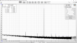
I used a similar battery pack to measure the loopback on the E-MU 0404 USB with the original Creative power adapter versus battery. Loopback alone is very close to identical. However in the next post I will show the difference when measuring an amplifier.
In this post in order there are:
- Left TS Output to B TS Input with original Creative power adapter.
- Left TS Output to B TS Input with battery pack.
- Left TRS Output to B XLR Input with original Creative power adapter.
- Left TRS Output to B XLR Input with battery pack.
Attachments
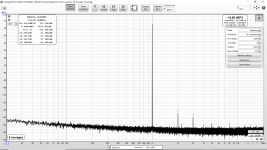
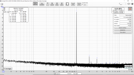
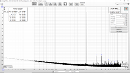
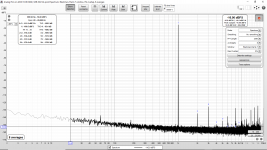
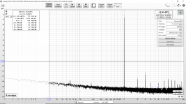
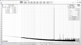
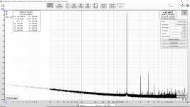
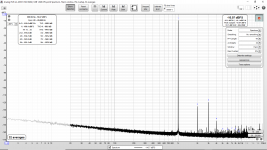
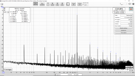
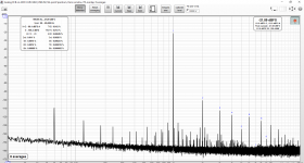
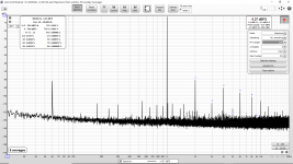
In this post I am measuring a uPC1342V based power amplifier with the E-MU 0404 USB. The degradation when using the original Creative power adapter with the 0404 is clear compared to the battery pack.
In this post in order there are:
In other words don't use that adapter. Use battery power if possible. Later I might try hooking up a linear regulator but the USB battery pack works well.
In this post in order there are:
- E-MU 0404 USB with original Creative power adapter (wall switcher)
- E-MU 0404 USB with original battery pack
- SB0490 (Sound Blaster Live! 24-Bit USB External, USB power)
In other words don't use that adapter. Use battery power if possible. Later I might try hooking up a linear regulator but the USB battery pack works well.
Attachments
-
 8 Vrms Original Creative Adapter Measure Across Load and Load Is From Designed Terminals.png192.7 KB · Views: 87
 -
 8 Vrms Battery Power Measure Across Load and Load Is From Designed Terminals.png144.6 KB · Views: 78
 -
 8 Vrms SB0490 Measure Across Load and Load Is From Designed Terminals.png170.3 KB · Views: 83
Last edited:
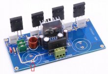
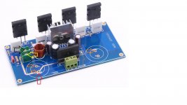
The PCB for this uPC1342V amplifier has a star ground formed by a number of different traces which emerge from the thru hole for one of the two main filter capacitors. I have attached a picture showing this.
Any suggestions on improving it?
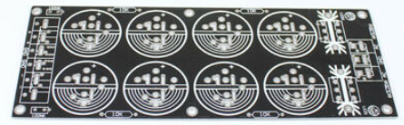
There is 2x4,700uF on the uPC1342V board and then 8x4,700uF on the rectifier board. (A picture of the bare board is attached.)
Any suggestions on improving it?
There is 2x4,700uF on the uPC1342V board and then 8x4,700uF on the rectifier board. (A picture of the bare board is attached.)
Attachments

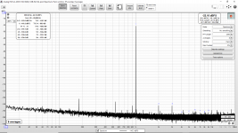
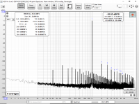
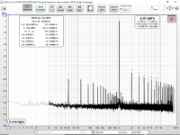
As a comparison the attached are in the same chassis with the same wiring and same power supply.
The first is an MX50X2 and the second is a QUAD405-2 modified (gain, current source and OPA228). These measurements are made by a desktop using an E-MU 1820m microdock attached to an E-MU 1010 PCI card. (Mains powered desktop.) These measurements were done before I bought the E-MU 0404 USB and before I built the balanced attenuator.
I am mystified as to why the uPC1342V measures so badly relatively speaking (THD, 2nd harmonic).
Attachments
Last edited:
kozard, can you describe or sketch the mains power input and how it interfaces to the power supply and how that gets to your amp board, and similarly how the input signal connects to your amp board. Is there a mains protective earth connection to something? Is the power supply floating? Is the speaker output signal connected back to that pcb star point somehow? ie. there is no clarity as to what forms a hum loop and how likely there is a common noise current path between signal input and speaker output, and between those points and a loop going back through mains wiring.
Last edited:
To start with here is a description of the current (partially disassembled) test setup:
Laptop is on battery power and the only connection is USB to the E-MU 0404 USB.
E-MU 0404 USB is powered by a 5V battery pack (internal 18650 cells).
Input to the amplifier comes from the E-MU left main output via a ¼” TS shielded cable (Gotham GAC-1) to a metal RCA plug.
The RCA plug connects to an input board connector which is not electrically connected to the chassis.
The input board connector board is connected via soldered Rapco CM Rated Installation Grade Mic Cable to the volume potentiometer board which is an Alps RH27. No electrical connection to the chassis.
The volume potentiometer board connects to the screw terminals on the pictured uPC1342V board via Rapco CM Rated Installation Grade Mic Cable. (Input connection point shown with grey arrow on attached picture.)
The power transformer is a 2x32VAC power transformer from an Onkyo power amplifier. The power transformer is currently external to the chassis and connects to the rectifier and filter board via three twisted 16 AWG Remington Industries tinned stranded copper wires. (External in an attempt to see if that reduced the power line harmonics, plus to try a different transformer.) The uPC1342V amplifier PCB has the option for the rectifier to be installed on the amplifier PCB but I did not do that. I used an external rectifier and filter board instead.
The power rectifier and filter board has 4x 120A Schottky rectifiers and 8x4700uF BC filter capacitors. (Picture of bare board attached.)
Previously the ground of the output side of the power rectifier board was connected to the chassis. I temporarily removed that as an experiment. Current (attached) results are with that ground removed temporarily. Later it will be attached again, perhaps with a 25A bridge, 10 Ohm and 100nF as per ESP.
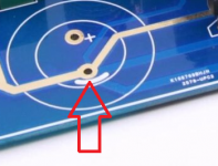
The power rectifier and filter board connects to the pictured uPC1342V board via three twisted 16 AWG Remington Industries tinned stranded copper wires which are soldered to the –ve terminal of the amplifier board negative filter cap, the star ground "integrated in the amplifier PCB layout" pictured in the attached picture (red arrow) and the +ve terminal of the positive filter cap. (Soldered under the board, three orange arrows on the attached picture.) The amplifier board filter capacitors are 4700uF Samyoung rescued/recycled from stereo amplifiers.
The output is taken at the yellow arrow shown on the attached picture of the uPC1342V board. I have experimented with two return paths. First to the black arrow on the attached picture of the uPC1342V board. (That is what the PCB designer intended.) Second to the ground on the output side of the power rectifier board (seems to be better). Both configurations produce about 4x the expected 2nd harmonic relative to the datasheet.
The load is currently two EBG UXP/300 10 Ohm in parallel (5 Ohms, my speakers are 4 Ohms) on a large heatsink. They are connected with 16AWG tinned copper stranded Beldon wire.
The input to the E-MU (Channel B XLR) is via the balanced attenuator mentioned previously in this thread. It is made of two 10k and two 270 ohm resistors which are matched better than 0.1%. (Connected across the EBG UXP/300 load. Slightly better results when connected directly to the output terminals on the amplifier PCB.)
The speaker protection board is current not in circuit.
Laptop is on battery power and the only connection is USB to the E-MU 0404 USB.
E-MU 0404 USB is powered by a 5V battery pack (internal 18650 cells).
Input to the amplifier comes from the E-MU left main output via a ¼” TS shielded cable (Gotham GAC-1) to a metal RCA plug.
The RCA plug connects to an input board connector which is not electrically connected to the chassis.
The input board connector board is connected via soldered Rapco CM Rated Installation Grade Mic Cable to the volume potentiometer board which is an Alps RH27. No electrical connection to the chassis.
The volume potentiometer board connects to the screw terminals on the pictured uPC1342V board via Rapco CM Rated Installation Grade Mic Cable. (Input connection point shown with grey arrow on attached picture.)
The power transformer is a 2x32VAC power transformer from an Onkyo power amplifier. The power transformer is currently external to the chassis and connects to the rectifier and filter board via three twisted 16 AWG Remington Industries tinned stranded copper wires. (External in an attempt to see if that reduced the power line harmonics, plus to try a different transformer.) The uPC1342V amplifier PCB has the option for the rectifier to be installed on the amplifier PCB but I did not do that. I used an external rectifier and filter board instead.
The power rectifier and filter board has 4x 120A Schottky rectifiers and 8x4700uF BC filter capacitors. (Picture of bare board attached.)
Previously the ground of the output side of the power rectifier board was connected to the chassis. I temporarily removed that as an experiment. Current (attached) results are with that ground removed temporarily. Later it will be attached again, perhaps with a 25A bridge, 10 Ohm and 100nF as per ESP.
The power rectifier and filter board connects to the pictured uPC1342V board via three twisted 16 AWG Remington Industries tinned stranded copper wires which are soldered to the –ve terminal of the amplifier board negative filter cap, the star ground "integrated in the amplifier PCB layout" pictured in the attached picture (red arrow) and the +ve terminal of the positive filter cap. (Soldered under the board, three orange arrows on the attached picture.) The amplifier board filter capacitors are 4700uF Samyoung rescued/recycled from stereo amplifiers.
The output is taken at the yellow arrow shown on the attached picture of the uPC1342V board. I have experimented with two return paths. First to the black arrow on the attached picture of the uPC1342V board. (That is what the PCB designer intended.) Second to the ground on the output side of the power rectifier board (seems to be better). Both configurations produce about 4x the expected 2nd harmonic relative to the datasheet.
The load is currently two EBG UXP/300 10 Ohm in parallel (5 Ohms, my speakers are 4 Ohms) on a large heatsink. They are connected with 16AWG tinned copper stranded Beldon wire.
The input to the E-MU (Channel B XLR) is via the balanced attenuator mentioned previously in this thread. It is made of two 10k and two 270 ohm resistors which are matched better than 0.1%. (Connected across the EBG UXP/300 load. Slightly better results when connected directly to the output terminals on the amplifier PCB.)
The speaker protection board is current not in circuit.
Attachments


Last edited:
- Home
- Design & Build
- Software Tools
- How to - Distortion Measurements with REW