There are two features to help with measurements made using a notch filter.
- In the Distortion settings there is an option to manually enter the level of the fundamental rather than have REW determine it from the input.
- To correct for the notch you can measure the notch filter response and use that to generate a calibration file which REW will apply to correct the harmonic levels. To do that I would make a sweep measurement of a loopback firstly with the notch filter in place, then another without it, then use the Trace arithmetic feature of the All SPL graph to generate (notch response)/(no notch response) and export that result as a text file to be loaded as a mic cal file. Alternatively you could just measure the notch response, offset the measurement so that the dB values correctly reflect the notch filter loss at the harmonics (the fundamental isn't critical since Manual fundamental deals with that) and export that offset notch response as text and load it as the mic cal file.
Are the noise, noise plus distortion and thd + noise calculations/RTA readouts "invalidated" by using a notch filter (calibration in the mic file)?
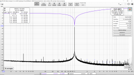
Please see the attached spectrum. The violet line is the measurement of the passive Hall notch filter.
Attachments
Use the latest V5.20 RC7 build, that has a wider (1 octave) notch for removing the fundamental region which will reduce the noise boosting effect of the notch cal file.
Ok. I tried RC7 this morning and the noise numbers look better.
With an 88 to 90 dB notch filter the levels end up at -240 dB or lower. So I guess I will need to use the math functions or Excel to change the 0 dB at 1 kHz (in the cal file) to -88 dB to fix that. (Offset the whole file by adding 88 dB?) I guess that will be the result of subtracting a measurement of the notch filter from a measurement of the interface with a straight loop-back.
Just FYI: I made the notch filter as stable as I can make it so far. However I am trying to calibrate and then measure immediately (without any delay).
Attachments

Last edited:
Offset the cal file so it has the correct gain figure away from the notch (e.g. measure a 100 Hz tone with/without). Use the Manual fundamental option in the Distortion settings to let REW know what level the fundamental should be, notch stability/drift shouldn't matter then.
Thank you. Yes, I should have done this:
Use the Manual fundamental option in the Distortion settings to let REW know what level the fundamental should be, notch stability/drift shouldn't matter then.
Do you have a way to measure the inductance? If not you might like to purchase a few of these to use as a baseline to complete the other resistor you are considering.
I ended up with 1uH.
But its not just about that. As keantoken said in my thread its about how the magnetic field from the collapsing inductance injections more harmonics into the measured signal.
AU $2.46 5%OFF | 10pcs 10W 5% Cement Resistor Power Resistance 0.1 ~ 10K 0.1R 0.5R 10R 50R 0.22 0.33 0.5 1 2 5 8 10 15 20 25 30 100 1K 2K 3K ohm
10pcs 10W 5% Cement Resistor Power Resistance 0.1 ~ 10K 0.1R 0.5R 10R 50R 0.22 0.33 0.5 1 2 5 8 10 15 20 25 30 100 1K 2K 3K ohm|Resistors| - AliExpress View attachment 936420 View attachment 936422
You want to use bulk metal resistors - they are non inductive and make a huge difference. The gold metal shells ones add distortion. The wire wound ceramics do as well.
The best ones are made by EBG. You can get used UXP-300 for about $15 on eBay. Not sure how much new but probably pricey. These are 300w 10ohm designed to be used with a heatsink like a CPU cooler or large aluminum plate.
For example:
QTY:10, EBG (VISHAY) UXP/300 10RK 10 OHM/10OHM 300W FOIL NON-IND.POWER RESISTOR | eBay
Another way is the series parallel quality 1W metal thin film resistors. You can make circa 25W dummy loads this way 5x5 8ohm config for example. Avoid metal oxide as they are distortion generators as well.
The worst ones are the huge 6in long 100w wirewound heater element style coated with green ceramic.
Just changing to EBG UXP-300 resistors and using a balanced input on my Focusrite with quality MKP caps cleaned up the measurements quite a bit.
Last edited:
Offset the cal file so it has the correct gain figure away from the notch (e.g. measure a 100 Hz tone with/without). Use the Manual fundamental option in the Distortion settings to let REW know what level the fundamental should be, notch stability/drift shouldn't matter then.
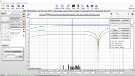
The attached images show how I did it.
In the first image there are the measurements "Straight_Loopback" and "Measured_Notch".
Next in "All SPL" I used Trace Arithmetic to calculate A/B where A is the "Measured_Notch" and B is the "Straight_Loopback". Make sure to get them in the right order. This result I called "Calculated_Cal_File" which I "Exported as txt". This exported file was setup as the microphone calibration file in the preferences.
I then entered a manual fundamental of 0.371Vrms because the Straight_Loopback (measured at the same level as I used in the generator for the distortion measurement) reads -8.6 dBFS. (And I put 1.000Vrms as full scale in the RTA.)
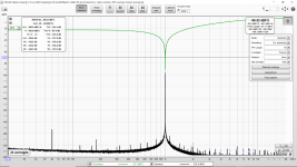
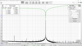
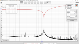
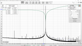
The results of the CS4392 with stock NE5532 output filter is attached as image 2. CS4392 with stock OPA2134 output filter is attached as image 3.
This might help someone else do their first measurements with a notch filter. A helpful dB to Voltage Gain/Loss calculator is found here: Decibels to Voltage Gain and Loss convert calculation conversion amplification amplifier electronics - sengpielaudio Sengpiel Berlin
Next I think I need to add an LNA and also upgrade the interface with ultra low noise supplies. Plus shield the notch filter plus LNA in a steel box.
Attachments
Last edited:
Can I bring up another question. I use REW a lot with shaped burst signals to test amplifiers without overheating them.
This works extremely well and REW is very flexible in setting up the signal parameters.
But such signals make it hard for a scope to trigger on, and what is needed is a sync signal, like the unmodulated signal, on the unused output channel of the soundcard.
Is it possible to send out different signals on the two channels of the soundcard? As far as I can see the REW generator can only output one signal to either or both channels. Is it possible to spawn another generator instance that sends another signal to a channel output? That way I could send the test signal out of Lch and the unmodulated sync signal out of Rch, for instance.
Jan
Jan, can you describe the burst you are using and why you can't trigger on an aspect of it. I presume you don't have a digital scope with signal acquisition storage of some kind.
I've used the tone burst for 2 cycle abnormal condition testing that could otherwise damage an amp - I was testing over-voltage protection performance - it can certainly be a useful tool.
I've used the tone burst for 2 cycle abnormal condition testing that could otherwise damage an amp - I was testing over-voltage protection performance - it can certainly be a useful tool.
I usually get good triggering by using a suitably long trigger hold-off so the trigger rearms in the interval between the bursts. I can add providing a separate signal to the feature request list though.
Hi John, good to see you here again!
Yes I think it could be quite useful, also for other types of tests, like running an amp while modulating the power supply.
Not your everyday need, but still.
I'll try the trigger hold-off. I am using a vintage Tek 2465.
Jan
Scarlett vs Clarett
Have not read every post, tried search but could not find the answer.
FWIW: At the moment I am reviving a HP 339A distortion analyzer. During this it appears the output of my computer is not optimal for my amplifier.
As a result I am now looking into an external USB sound card and the FocusRite Scarlett and Clarett came up. It would serve the additional purpose of being able to use the external sound card as a audio spectrum analyzer.
From the specifications I noticed that the Clarett will go all the way up to 35kHz @ -0.2dB. For pure listening that does not matter one iota, but how important is this for using it with REW and detecting the potential presence of higher harmonics/instability. Does the 20kHz vs 35 kHz matter?
I'm looking forward to your input on this.
Thanks
AM
REW can generate from at least 2Hz to the upper limit of soundcard (eg. 96kHz), so when the soundcard has a bandwidth inside those limits, then a loopback test has lower signal levels at the frequency ends, and so a calibration file inherently introduces more compensation and noise at the frequency extremes. The Clarett appears to have a wider raw bandwidth and lower distortion of both the available output ports and input ports, and appears to have a lower noise floor - they all add up to an improved measurement system. Although your interests may superficially be within the audio range, equipment sometimes shows up 'technical issues' such as instability with frequencies outside the audio range.
I like a 2-channel interface as it provides redundancy and test rig fault-finding benefits, as well as leveraging REW impedance measurement capability.
Powering is important imho. I'm pretty sure they are both powered by USB-C, and may need a high power port. Using with a laptop that can provide the required power from battery is important imho, as it removes earth related hum loop issues that sometimes can be a real pain.
The Scarlett 3 provides 1.5Mohm instrument input, which can be a benefit for simplified measurement of some signal circuitry. You'd have to email Focusrite to find out what the Clarett provided as it doesn't look like a published spec.
On AudioScienceReview are some informative reviews /measurements of the FocusRite Solo, 2i2 and the Clarett.
Teardown, few basic measurements and personal thoughts of the Focusrite Solo Gen3 | Audio Science Review (ASR) Forum
Focusrite Scarlett 2i2 Audio Interface Gen 3 Review | Audio Science Review (ASR) Forum
Focusrite Clarett 2Pre USB - quick measurements | Audio Science Review (ASR) Forum
The headphone output is nothing remarkable - not that we are really interested in that in our quest here (audio line out / spectrum analysis).
2-channel is simply a necessity when one wants to use it as an external sound card to drive some stereo amplifier. The Solo is therefor of no interest to me. The Clarett can drive 4 channels and can use 10 inputs.
If there is some oscillation going on outside the audio band then that is likely at quite some higher levels than the 2nd, 3rd, 4th, 5th and higher harmonics that we are interested in. As such the PicoScope 2204A (that I have - it has only a -55dB measurement capability) can pick that up.
The ASR measurements show that there is a narrow range in input /output levels where the FocusRite performs best. Some adjustable attenuators can be very useful - I've been looking on eBait at some pre-loved RF attenuators. Although they are 50 Ohms one could put a resistor in series (e.g. 450 Ohm, best made up from one 1K and 820 Ohm one parallel) and get 20dB attenuation (1:10 voltage). This allows the RF attenuator to operate in safe dissipation levels of an amplifier operating into 8 Ohms as they normally are only 1 or 2 watts input capable.
edit: Both my laptops are having USB-C high power connections and the Clarett can be powered through that.
Last edited:
The headphone output may allow lower impedance loads to be appropriately driven (such as with impedance measurement jig).
Parasitic oscillations can become noticeable as they rise out of the noise floor, and although the level may be really low it can indicate an unforeseen parasitic coupling. The noise floor level may rise appreciably outside of the audio band at higher frequencies, and noticeably mask harmonics, which the reviews don't often compare.
None of the reviews seem to touch on low frequency response, and few have phase shift responses out towards the REW limits, which may affect measurement performances at the outer limits where REW may be trying to calibrate to a flat response.
For really low noise floor and low distortion measurements at fixed 1kHz oscillator I use Victors oscillator. It has probably part per billion distortion and is battery powered ultra low noise floor. Alternatively is the Akitika 2ppm 1kHz oscillator. It works well too but not quite as low as Victors which can swing some high outputs since PSU I use is 4x 9v batteries for 36v supply.
I have Scarlett 2i4 and 2i2 and Solo. These are gen 2 ans old USB connector. When using on board DAC, the intrinsic distortion can be limiting. It can also cause amp to oscillate due to some strange feedback. Switching to external oscillator stops the feedback. This only happens on some amps.
I have run the 2i4 in ASIO mode at 192kHz. I normally run 96kHz. This let me look at FFT way past 20khz and I was surprised it was able to record data that high. Not sure how much of it was good as there might be internal filters.
For attenuators, I am using typically 22k and 2k CMF55 resistors as divider. Then 4.7uF MKP caps to couple balanced signal to 2i4. Make sure you connect the ground/shield pin to a GLB to the chassis of the amp - this really cuts out noise pickup. Post 538 shows how make the attenuator.
Howto - Distortion Measurements with REW
Last edited:
It can also cause amp to oscillate due to some strange feedback. Switching to external oscillator stops the feedback. This only happens on some amps.
This is probably what i was seeing when using the 2i2.
When testing a DUT with a soundcard, I'd aim to try and confirm that the DUT's input ground is connected to the DUT's output ground with a low impedance link that avoids any other signals from the DUT coupling in to any internal DUT ground link (and hence possible polluting the soundcard's measurement).
I have Scarlett 2i4 and 2i2 and Solo. These are gen 2 ans old USB connector. When using on board DAC, the intrinsic distortion can be limiting. It can also cause amp to oscillate due to some strange feedback. Switching to external oscillator stops the feedback. This only happens on some amps.
I was considering the FocusRite gen 3 until I discovered that with low headphone output impedance the performance of the headphone output was not very good. Noticeably the crosstalk was around -40dB. In most interfaces the headphone output seems to be something of an afterthought.
Good to know about potential oscillation - I know some tube amplifiers invert the signal or may even have some other strange speaker connection due to how output is connected. Certainly an item to watch out for.
- Home
- Design & Build
- Software Tools
- How to - Distortion Measurements with REW