The amplitude that the oscillator has to drive and the output impedance of the oscillator has an impact on the value. Make sure you are not asking an opamp of to drive a low impedance load at too high of an amplitude. 1Vpp is 0.353Vrms.
I cannot get any lower figure than 0.0033 THD irrespective of amplitude.
The Victor oscillator has 600R o/p impedance and is driving the 10K input impedance of the 2i2. The amplitude does not affect the o/p impedance.
The Akitika o/p amplitude does affect the o/p impedance because he uses a 10K pot on output - although it's still unlikely to be a problem.
How I got a number better than factory spec? Lucky unit?
Seems unlikely to me. The distortion is set by the design of the Focusrite input stage. I would be surprised if this varies from unit to unit by more than a few dBs.
Of course the other explanation is that I have a duff oscillator. I will have to test it with my friend's AP set - which will not be soon.
Am I using the right sort of cable to connect the oscillator to the 2i2 line-in?
I built one like this:
Van Damme RCA Phono to Mono Jack Cable. 6.35mm 1/4" Neutrik Lead HIFI Audio GOLD | eBay
I built one like this:
Van Damme RCA Phono to Mono Jack Cable. 6.35mm 1/4" Neutrik Lead HIFI Audio GOLD | eBay
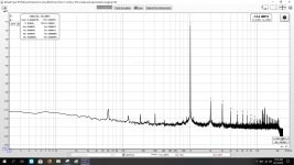
This is the distortion analysis of my M2X with Mountain View IPS, 2 v p-p, 1 watt, 4 ohms. Still has a large 60 hz and 120 hz wave, noise and distortion much lower. My Hafler 915 preamp was the cause of so much of the noise, it has a standby mode which has the preamp powered up, no output until switched on. I noticed a buzzing noise from the preamp in standby mode, once unplugged all my noise levels were reduced.
Attachments
Am I using the right sort of cable to connect the oscillator to the 2i2 line-in?
I built one like this:
Van Damme RCA Phono to Mono Jack Cable. 6.35mm 1/4" Neutrik Lead HIFI Audio GOLD | eBay
That might be your problem. You have a mono 6.35mm TS plug. What you want is a stereo TRS plug with the dummy load connected to T and R, leave S unconnected. On the mono plug, the R and S and shorted, so you are not using it in differential mode anymore.
You can also use an XLR male shell and wire your own connectors to pins 2 and 3:

Here is XLR to TRS balanced mode:

Do not connect to pin 1 (GND) which shorts one side of the differential input and possibly is making your source drive a much lower impedance load (a short to gnd?).
Last edited:
In a loopback test, my FR Solo gives 0.00055% using the Line input; the result is somewhat level sensitive. Switching over to the Instrument input makes it worse at 0.0031%.
Good to see someone else who is also managing to exceed the Focusrite factory spec for THD. That means that they conservatively rate their equipment (good).

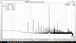
Another data point here, just measured the new WBA18 (Wayne's Burning Amp 2018 in Yarra daughterboard format) preamp module for the Yarra. It has a nice profile with dominant 2nd order. Driving 2.0Vpp into 52kohm load and using 2ppm 1kHz source with 2i4 and single ended RCA to XLR cable.

Here is the WBA18:
Here is the WBA18:
Last edited:

Any idea why the signal level on this is showing 70db or so? I can worry about the noise later (probably a fan plugged in on same circuit). Just wanted to figure out how to have my main test signal around 0.
EDIT: Why is it scaling my image down?
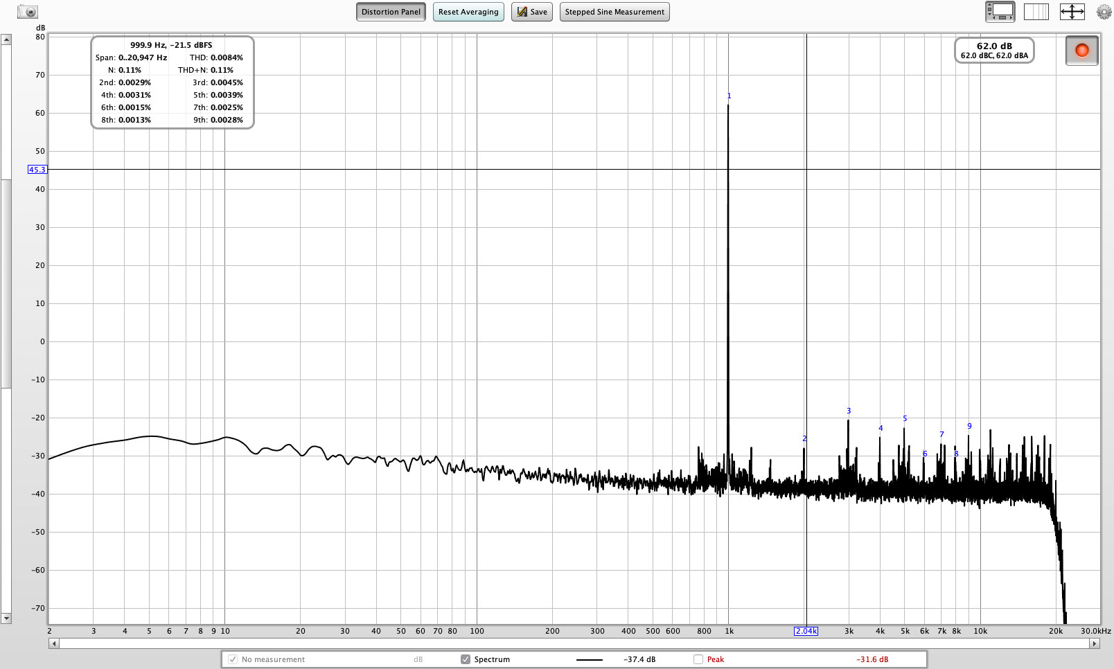
Change your vertical scale to dBFS. Then it will be relative to max of 0dB.
Thanks!! I wondered if that was the problem. Took forever to find where to do it though.
Now, if I wanted to measure a phono stage (which hopefully will show the limitations of my setup)...would I just crank the output way down on my interface box so as not to overload it? Any idea what dbFS level would approximate the sub mV range? Or is this not a good idea?
And on a side note...does anyone know why the system would be sizing down my images?
Change your vertical scale to dBFS. Then it will be relative to max of 0dB.
That might be your problem. You have a mono 6.35mm TS plug. What you want is a stereo TRS plug ...
I am now getting very similar THD measurements to yours.
Thanks!!
I am now getting very similar THD measurements to yours.
Thanks!!
Good to hear that the differential input TRS or XLR is important in getting the best measurement. Thanks for letting me know that it worked!
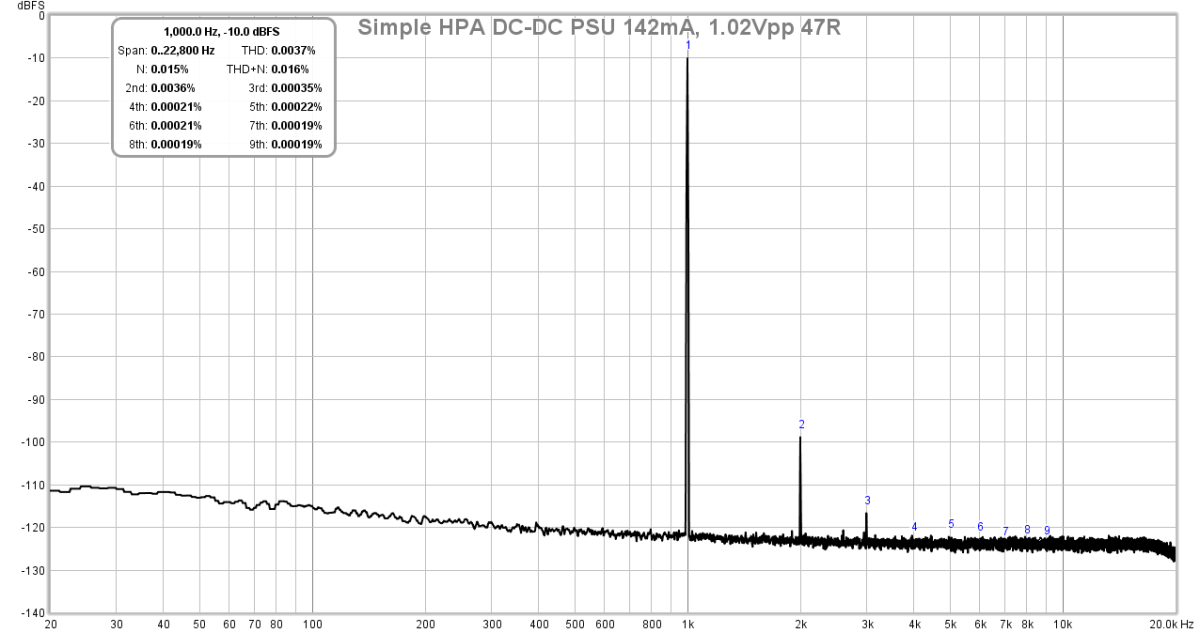
The rather tall "grass" we see at the noise floor is actual noise of the noise. When I used a 4uVrms noise TPS7Axxx voltage regulator as part of my headphone amp, the grass got a lot shorter. Interesting, how everthing matters. This was a super low noise, complicated PSU consisting of a Class 2 12v 1000mA wall wart, which then went to a CLC, then a DC-DC converter, a 4uVrms noise LDO linear regulator, a cap Mx, then a CRCRC, then to the amplifier.

Last edited:
- Home
- Design & Build
- Software Tools
- How to - Distortion Measurements with REW