^ I did notice that, and I had asked that in a prior post (#1649). I truly appreciate that you've taken the time to post a way to test that theory / potentially answer that question. I had been reading for a few hours trying to come up with something like what you've proposed.

Edited to add - the only variable that I could conceive of was the difference in the impedance of the DMM measuring the signal and the inputs to the Focusrite. That's what led me down that (clearly) awkward path of misunderstanding.
Edited again.. - rephrased... maybe more accurately... the variables that I was thinking around were the ratios of the output impedance of each generator vs. the 'input' impedance of the DMM / Scope / and Focusrite inputs.
Last edited:
^ Thank you. I am still trying to learn the proper terms and use them consistently.
Overall, I think I've learned that the ratio of the output / input impedance is important. I've tried to run a few experiments with no conclusive results yet.
I had posted in a different thread for a different purpose, but for the Shiba...
In the specifications section of the manual, it says...
3.1.1. Output Impedance · Balance/unbalance: 600 Ω terminator ON/OFF. Independently set for A and B channels.
In the operating instructions it says...
Push the “A&B 600 Ω LOAD” switch for turning ON (LED lights) to terminate the output with a 600 Ω resistor. When it turns OFF (LED goes out), output resistance selected is 600 Ω"
My measurements with DMMs and scopes at 1V agree when the LED is ON, which is where it has stayed, but perhaps that's not correct. I had posted in the other thread that the voltage essentially doubles with the light out (when measured with a scope / DMM). The manual is translated, and I fully admit that I haven't the foggiest clue re: what the section copied above really means. Another Shiba owner may help out. They clearly have way more experience with it and testing gear overall.
The specs for the Akitika say -
As an example, when I measure the output voltage of the Akitika ... It goes up to 2.96V Almost double the spec.
I am going to leave it until morning with fresh eyes and a fresh attitude / brain.
There is something fundamentally wrong with the way I'm either connecting gear and/or measuring the output voltages of the oscillators.
The common denominator is a short between the chair and the keyboard...
Seriously, thank you!
Overall, I think I've learned that the ratio of the output / input impedance is important. I've tried to run a few experiments with no conclusive results yet.
I had posted in a different thread for a different purpose, but for the Shiba...
In the specifications section of the manual, it says...
3.1.1. Output Impedance · Balance/unbalance: 600 Ω terminator ON/OFF. Independently set for A and B channels.
In the operating instructions it says...
Push the “A&B 600 Ω LOAD” switch for turning ON (LED lights) to terminate the output with a 600 Ω resistor. When it turns OFF (LED goes out), output resistance selected is 600 Ω"
My measurements with DMMs and scopes at 1V agree when the LED is ON, which is where it has stayed, but perhaps that's not correct. I had posted in the other thread that the voltage essentially doubles with the light out (when measured with a scope / DMM). The manual is translated, and I fully admit that I haven't the foggiest clue re: what the section copied above really means. Another Shiba owner may help out. They clearly have way more experience with it and testing gear overall.
The specs for the Akitika say -
- Maximum Output Level: 1.5 Volts RMS, adjustable
- Output impedance: 100 Ohms minimum to 2.5K maximum (depends upon level control setting)
As an example, when I measure the output voltage of the Akitika ... It goes up to 2.96V Almost double the spec.
I am going to leave it until morning with fresh eyes and a fresh attitude / brain.
There is something fundamentally wrong with the way I'm either connecting gear and/or measuring the output voltages of the oscillators.
The common denominator is a short between the chair and the keyboard...
Seriously, thank you!
Just so I can perhaps show more clearly what I'm experiencing and either confirm that I'm a complete dolt or help myself out of the 'is this guy serious?' box...
I will try very clearly to both show in pictures and describe a few things...
Here are two pictures of the initial balanced output settings from the ShibaSoku.
The first It shows the settings of 1Vrms output, balanced, with both + and - phase connected to the scope. Of note, the impedance button (light) is set to 600ohm load IN (light on).

This is a picture of the scope output for channels one (+ phase) and two (-phase). It's what I'd expect to see, and a DMM agrees with the scope and the displayed output voltage of the Shiba.

Here is another scenario. The only difference is that the impedance button is set to "out" and the light is off. The measured voltages double on the scope and the DMM. The displayed output voltage remains the same.


Here is the "SE" output of the Shiba at 1V with the light on.


Here is the "SE" output of the Shiba at 1V with the light off.

Here is the Akitika output at max output.

All voltages were cross-checked between the scope and a DMM for agreement.
Clearly the impedance of the Shiba has an impact. More to come after a brain rest... Note... another kind person had been trying to explain how the output of the Shiba along with the cabling and the input of the scope could be creating a voltage divider. I still must read more to try and understand that theory.
I'm not imagining the displayed results... I just haven't the foggiest of clues why I'm seeing what I'm seeing. That doesn't even get to the Focusrite interaction yet.
 to all.
I will try very clearly to both show in pictures and describe a few things...
Here are two pictures of the initial balanced output settings from the ShibaSoku.
The first It shows the settings of 1Vrms output, balanced, with both + and - phase connected to the scope. Of note, the impedance button (light) is set to 600ohm load IN (light on).
This is a picture of the scope output for channels one (+ phase) and two (-phase). It's what I'd expect to see, and a DMM agrees with the scope and the displayed output voltage of the Shiba.
Here is another scenario. The only difference is that the impedance button is set to "out" and the light is off. The measured voltages double on the scope and the DMM. The displayed output voltage remains the same.
Here is the "SE" output of the Shiba at 1V with the light on.
Here is the "SE" output of the Shiba at 1V with the light off.
Here is the Akitika output at max output.
All voltages were cross-checked between the scope and a DMM for agreement.
Clearly the impedance of the Shiba has an impact. More to come after a brain rest... Note... another kind person had been trying to explain how the output of the Shiba along with the cabling and the input of the scope could be creating a voltage divider. I still must read more to try and understand that theory.
I'm not imagining the displayed results... I just haven't the foggiest of clues why I'm seeing what I'm seeing. That doesn't even get to the Focusrite interaction yet.
to all.Fairly obvious that the output impedance of the Shiba is high relative to the low ipedance of the mic input. There is no magic going on and cabling etc is not relevant.
If you'd never tried the mic input you'd never have been diverted by this simple fact.
Put a resistor of 3k across the DMM input and see what happens......
If you'd never tried the mic input you'd never have been diverted by this simple fact.
Put a resistor of 3k across the DMM input and see what happens......
You can easily calcuate the Shiba output impedance using Ohm's law.
Let's say the voltage drops to 0.75v into the 3k inut impedance, meaning a current of 250Ua is flowing. This is causing the drop of ,25v so the impedance is 0.25/.00025 = 1k ohms. Or in this example, the ratio of voltage drop is 3:1 so the impedance ratio is the same i.e 3:1 = 3k to 1k.
In dbv terms the drop is -2.5db ref 0dbv = 1v rms.
^ The help is greatly appreciated.
You seem to want to emphasize that you knew it, but others didn't. I've read this thread a number of times. Unless I've missed something... which is likely; until my issue came along, it's the first time I've seen you (or anyone) advise against using the mic inputs. A non-zero number of people have advised using them. So... here we are. Some of us don't mind making errors to learn. No worries on my part, and seriously, I truly do appreciate the time you've taken to help me understand. If you hadn't put your one-liner in the middle of a response to another person, I certainly would have never known to try the line level, and I'd still be off in the distance.
After another coffee, I've got a few learning exercises to try including the one you've listed.
Edited to add - Also, your advice around not using the mic inputs seemed to be based around relative noise at higher input voltages vs. relative impedances. So... the Shiba (I'd assume) would still show this 'issue' at the mV output range when used with the Focusrite Mic input. I'm a silver lining kind of person... so, now I know that even at input voltages for which the mic input is 'more appropriate' that the 'impedance mismatch' would still cause issues. I'll still test that, but it's valuable information... I think.
Simple is relative. While true, a person who's advice has yet to steer me wrong advised using the mic input. They could not have known the relative impedances. I still consider them an excellent source for advice. We all learn together.If you'd never tried the mic input you'd never have been diverted by this simple fact.
You seem to want to emphasize that you knew it, but others didn't. I've read this thread a number of times. Unless I've missed something... which is likely; until my issue came along, it's the first time I've seen you (or anyone) advise against using the mic inputs. A non-zero number of people have advised using them. So... here we are. Some of us don't mind making errors to learn. No worries on my part, and seriously, I truly do appreciate the time you've taken to help me understand. If you hadn't put your one-liner in the middle of a response to another person, I certainly would have never known to try the line level, and I'd still be off in the distance.
After another coffee, I've got a few learning exercises to try including the one you've listed.
Edited to add - Also, your advice around not using the mic inputs seemed to be based around relative noise at higher input voltages vs. relative impedances. So... the Shiba (I'd assume) would still show this 'issue' at the mV output range when used with the Focusrite Mic input. I'm a silver lining kind of person... so, now I know that even at input voltages for which the mic input is 'more appropriate' that the 'impedance mismatch' would still cause issues. I'll still test that, but it's valuable information... I think.
Last edited:
I own both the UCA202 and the Motu M4. The Motu Line Input has a low impedance of 5kOhms and in case of overload the input tranzorb diodes melt down. Needs very careful handling when measuring power outputs. The mic input has increasing THD with low gain settings. This is obviously due to the THAT PreAmp with its internal switched gain blocks. To reach the very good performance of its Codecs I implemented my own line-input. Yes, the MOTUs are excellent, but obviously they are not designed for measurements.
^ I'm still working on my measurements for dummies testing... but that's also valuable information.
Up until well.... a day or so ago... I had never once considered how one piece of test gear might interact with another with regards to their relative input/output impedances. This seems particularly true when we (I) seem to be repurposing a DAC / ADC intended for other purposes as a piece of measurement equipment. As others have kindly noted.. had I done it properly in the first place...")
Using this type of setup and an external oscillator seems like it's not a bad idea for those that know what they're doing... for me... it's been a fun / frustrating learning experience. If another person that finds themselves in a similar spot saves themselves a moment's frustration by reading my rambles.... perfect.
With that said, I've done about 100 measurements, so far, and I'll run them through an ANOVA / regression or just do some simple math to try and determine what's going on with the 'switch' from the Shiba.
Overall, know thy gear... I guess.
Up until well.... a day or so ago... I had never once considered how one piece of test gear might interact with another with regards to their relative input/output impedances. This seems particularly true when we (I) seem to be repurposing a DAC / ADC intended for other purposes as a piece of measurement equipment. As others have kindly noted.. had I done it properly in the first place...
Using this type of setup and an external oscillator seems like it's not a bad idea for those that know what they're doing... for me... it's been a fun / frustrating learning experience. If another person that finds themselves in a similar spot saves themselves a moment's frustration by reading my rambles.... perfect.
With that said, I've done about 100 measurements, so far, and I'll run them through an ANOVA / regression or just do some simple math to try and determine what's going on with the 'switch' from the Shiba.
Overall, know thy gear... I guess.
So, I had some fun. I may have even learned something. My measurements were crude, but I think effective. In hindsight, I should have measured the resistance of each resistor. However, I used the same resistors for each measurement, and they were advertised as 1% resistors.
Attached are a few files if anyone wants data.
Summarized...
My Akitika oscillator output impedance measures between 104 (Average) and 2301 (Average) ohms. It varies based on output just like the specs say. No surprise to its designer or to any of you. What was interesting (to me) is that at max output, the output impedance drops back down. I'm sure the reason behind that is obvious to many of you, but I'm still scratching my head. I used 1k, 3k, 10k, 30k, 60k and 1M resistors for the measurements and calculations. I tossed the 1M results b/c .... they looked funny. It's likely my measurement error / rounding errors, my Excel skills, my math skills, or some other thing that I don't quite understand at the moment. The voltages below were not exactly as posted. I rounded. The sheet attached has the actual data. I also don't understand why my Akitika has a maximum output voltage of nearly twice the posted specification. Perhaps it's a build error. If anyone else has seen similar, I'd love to know.
Next - I wanted to see if the ShibaSoku had an output impedance that varied with output level like the Akitika. I also wanted to try and determine just WTF that button really does. Again... this is simple stuff for many of you, but I had some fun... and I hope learned a little. I also wanted to see if the ShibaSoku had a particularly "high" output impedance as some of you were threorizing may contribute to my "wonky" results when using the Focusrite's Mic input. I used a wider range of resistors, but again... in the results posted below, I culled the results from the higher resistance values similar to the Akitika b/c... ??
The output impedance remains relatively stable across a range of voltages. Turning the 'switch' off (noted as 600 ohm load out) roughly doubles the output impedance from ~300 ohms to ~600 ohms. So... yay. With that said, the scopes / DMMs have input impedances in the Mohm range, so I am still flummoxed why I get a measured 'double' voltage output when the switch is in this position.
Restated slightly; When the switch is ON '600 ohm load IN', I measured roughly 300 ohms output impedance. Again, the switch in this position agrees with DMM and oscilloscope measurements. Why? I am still learning...
So...
Given that the Akitika's output impedance ranges even higher than the relatively stable ShibaSoku AND that the measurements in question were done at 1Vrms with the 'light on'. The Shiba's Zout was ~300 ohms give or take, while the Akitika's was ~2300 ohms give or take. So, the theory of a relatively 'high' output impedance from the ShibaSoku contributing to the measurement difference needs further investigation. I can't confirm that theory with my measurements. It sure was fun to try though!
Any other thoughts?
Edited to add the zipped Excel file with the raw data.
Attached are a few files if anyone wants data.
Summarized...
My Akitika oscillator output impedance measures between 104 (Average) and 2301 (Average) ohms. It varies based on output just like the specs say. No surprise to its designer or to any of you. What was interesting (to me) is that at max output, the output impedance drops back down. I'm sure the reason behind that is obvious to many of you, but I'm still scratching my head. I used 1k, 3k, 10k, 30k, 60k and 1M resistors for the measurements and calculations. I tossed the 1M results b/c .... they looked funny.
It's likely my measurement error / rounding errors, my Excel skills, my math skills, or some other thing that I don't quite understand at the moment. The voltages below were not exactly as posted. I rounded. The sheet attached has the actual data. I also don't understand why my Akitika has a maximum output voltage of nearly twice the posted specification. Perhaps it's a build error. If anyone else has seen similar, I'd love to know.| Output Voltage with DMM | Calculated Zout |
| Avg 25mV | 117 |
| Avg 100mV | 368 |
| Avg 500mV | 1,454 |
| Avg 1000mV | 2,275 |
| Avg 2000mV | 2,301 |
| Avg 2940mV | 104 |
Next - I wanted to see if the ShibaSoku had an output impedance that varied with output level like the Akitika. I also wanted to try and determine just WTF that button really does. Again... this is simple stuff for many of you, but I had some fun... and I hope learned a little. I also wanted to see if the ShibaSoku had a particularly "high" output impedance as some of you were threorizing may contribute to my "wonky" results when using the Focusrite's Mic input. I used a wider range of resistors, but again... in the results posted below, I culled the results from the higher resistance values similar to the Akitika b/c... ??
| Using only 1k through 30k. Zout | ||
| Light On | Light Off | |
| Avg 25mV | 305 | 574 |
| Avg 100mV | 304 | 594 |
| Avg 500mV | 309 | 584 |
| Avg 1000mV | 299 | 598 |
| Avg 2000mV | 298 | 576 |
The output impedance remains relatively stable across a range of voltages. Turning the 'switch' off (noted as 600 ohm load out) roughly doubles the output impedance from ~300 ohms to ~600 ohms. So... yay. With that said, the scopes / DMMs have input impedances in the Mohm range, so I am still flummoxed why I get a measured 'double' voltage output when the switch is in this position.
Restated slightly; When the switch is ON '600 ohm load IN', I measured roughly 300 ohms output impedance. Again, the switch in this position agrees with DMM and oscilloscope measurements. Why? I am still learning...
So...
Given that the Akitika's output impedance ranges even higher than the relatively stable ShibaSoku AND that the measurements in question were done at 1Vrms with the 'light on'. The Shiba's Zout was ~300 ohms give or take, while the Akitika's was ~2300 ohms give or take. So, the theory of a relatively 'high' output impedance from the ShibaSoku contributing to the measurement difference needs further investigation. I can't confirm that theory with my measurements. It sure was fun to try though!
Any other thoughts?
Edited to add the zipped Excel file with the raw data.
Attachments
Last edited:
^ Thank you. Another person had mentioned that also. That seems to not necessarily have been dismissed, but ... maybe it's related but separate.
I will ALWAYS admit when I just completely don't even understand the most simple of things, but if you could really, really dumb it down...?
The displayed output on the oscillator does not change when the button is pressed.
Switch lit (600 Ohm Load In) - Voltage Measurements with a DMM and oscilloscope match the display.
Switch unlit (600 Ohm Load Out) - Measurements with a DMM and oscilloscope are roughly double what are displayed.
I seriously don't want anyone to go out of their way, but I do understand the schematics of a voltage divider. Could you sketch what you're thinking?
Does anyone happen to know in what use case someone would press or not press the button? I'm sure it's there for a very good reason. I'll admit my total ignorance even after reading 100's of pages. It's an oscillator. Why would you load the input vs. output. There's only an output...
Something is just not clicking... except the relays on the Shiba. Gotta joke when I'm frustrated.
I will ALWAYS admit when I just completely don't even understand the most simple of things, but if you could really, really dumb it down...?
The displayed output on the oscillator does not change when the button is pressed.
Switch lit (600 Ohm Load In) - Voltage Measurements with a DMM and oscilloscope match the display.
Switch unlit (600 Ohm Load Out) - Measurements with a DMM and oscilloscope are roughly double what are displayed.
I seriously don't want anyone to go out of their way, but I do understand the schematics of a voltage divider. Could you sketch what you're thinking?
Does anyone happen to know in what use case someone would press or not press the button? I'm sure it's there for a very good reason. I'll admit my total ignorance even after reading 100's of pages. It's an oscillator. Why would you load the input vs. output. There's only an output...
Something is just not clicking... except the relays on the Shiba.
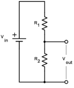
Gotta joke when I'm frustrated.A voltage divider is two resistors in series as load and the output is the common connection of the series resistors... A potentiometer is often used as a voltage divider.
In the image attached, R1 would be the output impedance and R2 would be the load that is switched in or out.
In the image attached, R1 would be the output impedance and R2 would be the load that is switched in or out.
Attachments
With the 600 ohm load in place, the oscillator's voltage output versus frequency into a high input impedance device-under-test will not vary much. Look at your data and see how the voltage varies across various resistors with a set fixed output voltage, with and without the 600 ohm load in place.
^ From #1673 - Yep. I understand that piece. The manual says this.
3.1.1. Output Impedance · Balance/unbalance: 600 Ω terminator ON/OFF. Independently set for A and B channels.
Push the “A&B 600 Ω LOAD” switch for turning ON (LED lights) to terminate the output with a 600 Ω resistor. When it turns OFF (LED goes out), output resistance selected is 600 Ω"
I had sketched below when trying to interpret the manual...

I interpreted as the 600 ohms was the output impedance (600R). The display on the oscillator would always display Vs. When the light is on indicating "to terminate the output with a 600 ohm resistor", I assumed ZL was "added" as 600 ohm. When the light was off, there was no Zl.
Is what you're (and at least one other person) thinking that from the standard diagram of the voltage divider you posted, that I am pretty sure I understand ... that a resistor is added in series to create a divider? If so, I completely and totally misinterpreted the manual (among many, many things).
From #1674 - Agreed. Totally cool with that. If the input impedance on the DUT (or the input of the ADC) is high enough. No worries. It was (and still is) related to yet another mystery that I cannot solve. I'll hold on that with one piece at a time.
Thank you!
Edited... sheesh... I posted the new photo I just drew vs. the one from last night. ... Shows how my brain is totally messed up. Is that what's likely happening?
3.1.1. Output Impedance · Balance/unbalance: 600 Ω terminator ON/OFF. Independently set for A and B channels.
Push the “A&B 600 Ω LOAD” switch for turning ON (LED lights) to terminate the output with a 600 Ω resistor. When it turns OFF (LED goes out), output resistance selected is 600 Ω"
I had sketched below when trying to interpret the manual...
I interpreted as the 600 ohms was the output impedance (600R). The display on the oscillator would always display Vs. When the light is on indicating "to terminate the output with a 600 ohm resistor", I assumed ZL was "added" as 600 ohm. When the light was off, there was no Zl.
Is what you're (and at least one other person) thinking that from the standard diagram of the voltage divider you posted, that I am pretty sure I understand ... that a resistor is added in series to create a divider? If so, I completely and totally misinterpreted the manual (among many, many things).
From #1674 - Agreed. Totally cool with that. If the input impedance on the DUT (or the input of the ADC) is high enough. No worries. It was (and still is) related to yet another mystery that I cannot solve. I'll hold on that with one piece at a time.
Thank you!
Edited... sheesh... I posted the new photo I just drew vs. the one from last night. ... Shows how my brain is totally messed up. Is that what's likely happening?
Last edited:
From #1674 - Agreed. Totally cool with that. If the input impedance on the DUT (or the input of the ADC) is high enough. No worries. It was (and still is) related to yet another mystery that I cannot solve. I'll hold on that with one piece at a time.
The DUT's input impedance would be in parallel with the 600 ohm load so the effective voltage divider will have changed. If the DUT's input impedance varies with frequency, then the input voltage will vary with frequency. However, for high input impedance, when paralleled with the low impedance load (600 ohms), the 600 ohms won't change much.
What pinholer said. When the switch is off the output impedance is 600R. When the switch is on, a 600R is added across the output.
So the output voltage displayed is only correct when the switch is on, with 600R across the output. When the switch is off, the output voltage is twice the displayed voltage. That is a good reason to measure the output voltage rather than trust the voltage displayed on the generator's meter.
The output impedance is low enough that the input impedance of the Focusrite is not an issue.
The Akitika's output impedance being much higher would affect the output voltage of the Focusrite, and that is shown in the difference between the TRS and XLR FFTs.
From #1676 - Nice! So, a mightily huge thanks to both you and @rsavas! I have to give him a shout out too b/c he led me down that road before I completely misinterpreted. I now grasp why it measures how it does. I still haven't the foggiest idea of its practical use, but... that's for another day.
@Ben Mah - Yep. It wasn't an issue with the Shiba's Zout being high. The Zout of the Shiba is relatively stable. It was an issue with the Akitika's being higher (at that Vout) combined with the lower Zin of the Focusrite.
Anyway.... I (and all of you) deserve a break. I have learned a tremendous amount. It may not seem like much to the experts, but when I actually understand something down to a "first principle" level, it usually sticks with me. I had fun doing the lab work. Most of you had it solved in your head before even seeing more information, but I clearly needed the bonk on the head a few times.
Last edited:
- Home
- Design & Build
- Software Tools
- How to - Distortion Measurements with REW