That circuit was given as having a 23kHz cutoff, I think. But it's going to depend on the input impedance of your soundcard. What is the input impedance of your mic input? 1K-2K? Line input is probably 10K.I tried 100nF+100ohms before that but that was a complete fail, distortion exploded (arround -70db), maybe I should try again since I ajusted divisor
That circuit was given as having a 23kHz cutoff, I think. But it's going to depend on the input impedance of your soundcard. What is the input impedance of your mic input? 1K-2K? Line input is probably 10K.
Right, low pass filter. Impedance is not stated anywhere in specs but as per my multimeter minimum impedance would be 12KO Hot/Cold (balanced) or 6KO Hot to shield/pin1 (unbalanced). If that's relevant I should go for a much lower capacitance value. I have 680pF but that's CMS, I'll try to find a way
You will get results more quickly from coherent averaging with a shorter FFT, 64k or 128k. Above 128k averaging gets slower as the overlap limit is reached.Coherent distortion and more decimals on frequency
Thank you, it's all clear now.W
@jan.didden
If you want to analyze a multitone response with REW you should also generate it with REW so that REW 'knows' all the parameters.

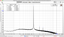
Test @ 192kHz
Attachments
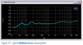
The next step now becomes, what can we get from such a multitone response?
For instance, if you connect the peaks of all the signals, you have the frequency response.
If you set it up smartly, you can measure noise in the presence of signal from bins where only noise can fall, see attachment.
And several measurements more. How do you extract HD and IMD from the response? These are the important discussions.
Jan
Attachments
Last edited:
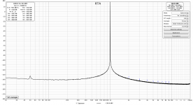
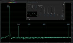
I am testing the coherent averaging as it yields visually quite different results to magnitude averaging.
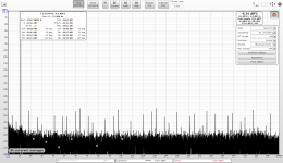
Fundamental 1,125Hz fits exactly bin center at 64k FFT and 48kHz samplerate
1,125Hz / (48,000Hz/2^16 bins) = 1,536th bin.
Testing with distortion calibration and compensation continously running on ADC side, i.e. the harmonics are being removed from the recorded signal with the calibration profile updated every 2 seconds.
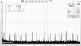
Chart 1 - magnitude averaging at 64k FFT - the harmonics are within the noise.
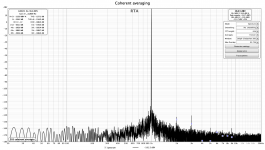
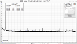
Chart 2 - coherent (vector) averaging at 64k FFT - the harmonics are still within the noise, the noise is averaged-out significantly.
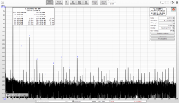
Chart 3 - H2, H4, H5 at -150dBFS are added after distortion compensation
Chart 4 - H2, H4, H5 at -155dBFS are added after distortion compensation (I left the averaging running for a while)
Chart 5 - H2, H4, H5 at -160dBFS are added after distortion compensation
In all cases the added distortion is shown filtered out from the noise of the soundcard. The -160dBFS distortions are identifed slightly higher, this may already approach precision of the distortion generator (chebyshev polynomials).
It looks the algorithm is working correctly.
Fundamental 1,125Hz fits exactly bin center at 64k FFT and 48kHz samplerate
1,125Hz / (48,000Hz/2^16 bins) = 1,536th bin.
Testing with distortion calibration and compensation continously running on ADC side, i.e. the harmonics are being removed from the recorded signal with the calibration profile updated every 2 seconds.
Chart 1 - magnitude averaging at 64k FFT - the harmonics are within the noise.
Chart 2 - coherent (vector) averaging at 64k FFT - the harmonics are still within the noise, the noise is averaged-out significantly.
Chart 3 - H2, H4, H5 at -150dBFS are added after distortion compensation
Chart 4 - H2, H4, H5 at -155dBFS are added after distortion compensation (I left the averaging running for a while)
Chart 5 - H2, H4, H5 at -160dBFS are added after distortion compensation
In all cases the added distortion is shown filtered out from the noise of the soundcard. The -160dBFS distortions are identifed slightly higher, this may already approach precision of the distortion generator (chebyshev polynomials).
It looks the algorithm is working correctly.
Attachments
Last edited:
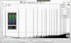
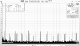
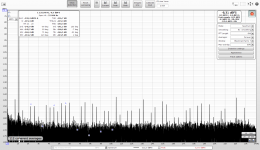
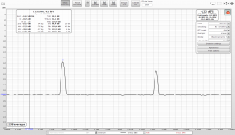
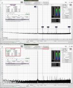
Source signal is generated by REW (1,125Hz):
REW -> my compensation SW -> E-MU 0404 (average distorting - see the attached spectrum) -> the distortion calibration adapter (it has no role in this measurement) -> E-MU -> compensation SW running combined-sides calibration + compensation + adding the distortions to the compensated signal -> REW.
The averaging does not "surpress" all non-harmonic bins as there are hairs at -145dB left. No idea what that is, maybe calculation artefacts.
I used specifically 1,125Hz to avoid 64k FFT bin leakage.
I can try adding some non-harmonic tone.
Attachments
Last edited:
Perhaps easier to test with a file. 1125 Hz is quite problematic for 48 k (or multiples) sampling from a quantisation perspective, needs dither. I tweaked the signal generator so I could add harmonics at -180 dB and added the lowest dither I have implemented (25th bit) to 997 Hz on a 60s file saved as 32-bit float:

I did rebuild my measurement setup based on balanced classD attenuator shown post #283, and that works quite well.
2 questions however :
2 questions however :
- what is the purpose of the capacitor in series (1uF) ? i would understand the need for Low pass filter but why a High pass filter in there ?
- If I switch polarity at the amp output THD has a slighly different value with slightly different harmonic profile. Is that because polarity change harmonic's phases and then harmonics adds/substracts differently with soundcard's harmonics ?
Attachments
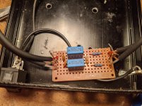
Well, it looks more like that the blue ones are in series and the small ones are in parallel... that makes sense - no?
//
Yes but that's my build ! I added the parallel ones (low values), these are not in post #283.
My guess is that the caps in series are DC blocking. Many small Class-D amps with single rail supplies have outputs that ride at 1/2 supply voltage.
Ok thanks for the lead Pano. I finaly took them off as I saw no difference in THD results and these caps were obviously arming other type of measurements such as frequency response (Tested on ncores and cheap Alientek D8).
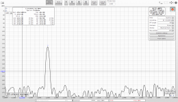
Macbook Pro (late 2013) Loopback Test
Just for grins and to learn REW, I built a loopback for my Macbook - sending the headphone output back into the external mic input via an attenuator.
The Macbook, in order to be faked out for external mic detection, needs about a 1.6K resistor across the mic input. I used a splitter to separate output and input.
THD is not so bad (.0038%), but noise is pretty bad (.033%), as is often the case with built-in sound devices. Not sure if this will be useful for actual amplifier testing, or if I will need to pony up for a Focusrite (or other external device). We'll see.
Attachments
- Home
- Design & Build
- Software Tools
- How to - Distortion Measurements with REW