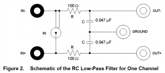
There is some very good literature online about measuring Class-D amps. Analog Precision has some info about it.
AUX-0025 / 0040 / 0100 Switching Amplifier Measurement Filters - Audio Precision
AUX-0025 / 0040 / 0100 Switching Amplifier Measurement Filters - Audio Precision
Non, pas de tout! Mais I see Schmilblick and that takes me back to France and a certain era. Do kids today even know?mon anglais est si mauvais.
")
Still, just to be clear, I don't really care about getting absolute correct results, I know I can't given low quality measurmeent setup I use.
What I need is mostly that results are consistent and reliable in my specific setup, so if I change anything to amp I can measure if its good, bad or useless.
All measurement I attached up to now are stock left channel. I did some mods to right channel which I measured as beeing some improvements compared to left. And whatever the soundcard input, Line or MIC, improvement is still there.
Tell me if I'm fooling myself here.
Attached are :
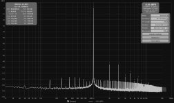
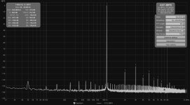
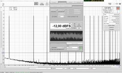
1/Left (Stock channel) measured with MIC input
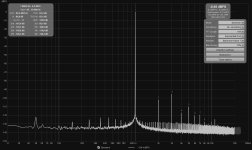
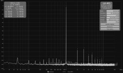
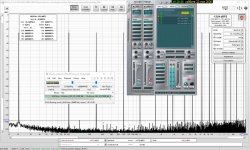
2/ Right (modded) with MIC input
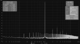
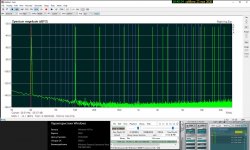
3/ Left with Line input and
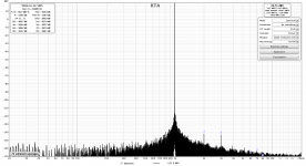
4/ right with Line input
What I need is mostly that results are consistent and reliable in my specific setup, so if I change anything to amp I can measure if its good, bad or useless.
All measurement I attached up to now are stock left channel. I did some mods to right channel which I measured as beeing some improvements compared to left. And whatever the soundcard input, Line or MIC, improvement is still there.
Tell me if I'm fooling myself here.
Attached are :
1/Left (Stock channel) measured with MIC input
2/ Right (modded) with MIC input
3/ Left with Line input and
4/ right with Line input
Attachments
-
 2020 05 21-Ncore RME Shield THD Gauche MICXLR 4ohms 5W -29.5dBr.jpg198.3 KB · Views: 295
 -
 2020 05 21-Ncore RME Shield THD Droite MICXLR 4ohms 5W -29.5dBr.jpg195.5 KB · Views: 289
 -
 2020 05 16-Ncore RME Shield THD Gauche 4ohms 5W -29.5dBr.jpg196.9 KB · Views: 283
 -
 2020 05 18-Ncore RME Shield THD Droite PlaqueMetal+CablesHPrefaits 4ohms 5W -29.5dBr.jpg193.5 KB · Views: 99
Last edited:
Non, pas de tout! Mais I see Schmilblick and that takes me back to France and a certain era. Do kids today even know?
For sure they don't, my kids have no clue what this word is. But now I know you're definitly a quite cultivated man !
I see a lowering of the spuria and maybe a change in the harmonics. It's all very low.
Yes it is. I'm not sure the THD difference on MIC input is reliable but lowered spuria is for sure reliable : sticking my ears on left tweeter, I can ear a very low SMPS noise while right tweeter is dead silent.
I know we usually don't listen to music with ears sticked to tweeters but I like making good things even better with cheap solutions !


loopback = foobar-CS4398 @ АК5394 - REW & ARTA
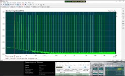
Vovi what source did you use, the REW multitone generator? The tones seem all geometrically spaced. I think that normally the spacing would be adapted to make sure the distortion products fall in otherwise empty bins. In REW you would check the NIB checkbox ('No Interharmonic Distortion').
But I may miss something here.
Jan
Last edited:
Thanks, I am not familiar with the multitone in ARTA but it appears that it is simply geometrically spaced with no provisions to sort out harmonics and noise and/or limit crest factor.
If you test it with REW I would suggest to use the REW multitone generator with NIB checked, to get a consistent analysis.
Jan
If you test it with REW I would suggest to use the REW multitone generator with NIB checked, to get a consistent analysis.
Jan
Hmmm, right, high switching frequency at the output, thanks for bringing that up...
To bad I can't measure that switching noise. At least that would explain why I get better results on MIC input with both loopback and RME but worst with Amp + voltage divisor.
My voltage divisor is fully balanced, I can set pin 1 reference to whatever I choose, exactly as you described Pano. Trust me there is no better result here than biting negative Amp output. Connecting to Amp ground (class1, earthed) is a noise festival, arround -85db.
Amp is the only one earthed, measurement chain is : ShieldTV playing REW's 1khz wav signal (resampled to 192Khz thanks to Android...) to RME ADI2 DAC balanced to double Ncores.
As a follow up, I ajusted the voltage divisor so the Amp ouput dbFS level into the soundcard's MIC input is the exact same as RME DAC into same soundcard input. SINAD are now what they were before, not better but at least consistent between channel left and right. THD and N distribution is different but THD+N is same.
I tried 100nF+100ohms before that but that was a complete fail, distortion exploded (arround -70db), maybe I should try again since I ajusted divisor.
As previously, first is LeftC, second is RightC.
Attachments

Last edited:
jan.didden
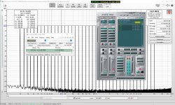
...I am not familiar with the multitone in ARTA
Following multitone signals are implemented in ARTA:
• Wideband range 1/3 octave spaced sine signals from 20 ẟf to fs/2. Crest factor is 12 +\- 1 dB.
In the attachment @ test REW multitone signals
Attachments
Multitone is a very powerful technique that can show, from a single measurement, things like harmonic distortion, intermodulation distortion, THD+N, noise only in the presence of signal, frequency response etc.
For that to work, each tone must be precisely placed in relation to the other tones and also related to the selected FFT parameters.
From the REW help:
The multitone generator produces multiple tones over a defined frequency span. The tones can be spaced linearly, logarithmically at a selected fractional octave or fractional decade interval or in a sequence that places the tones such that they do not correspond to the low order harmonic or intermodulation products of other tones ('No Interharmonic Distortion' or NID). Octave fraction spacing uses frequencies from the preferred list. In all cases the tones are placed at the bin centres of an FFT of the selected sequence length, so that the behaviour of a system fed by the tones can be observed on an FFT with at least that length using a rectangular window (Bold mine)
This will not be the case if you generate the multitone with one app and the measurement with another app. If you want to analyze a multitone response with REW you should also generate it with REW so that REW 'knows' all the parameters. In your graph, the numbers of the harmonics in the REW graphs indicate that REW is 'confused', sort of, because it does not know what the signal is, what the fundamental is. It 'thinks' the 100Hz is the fundamental and 'thinks' that everything else must be harmonics of 100Hz. The indicated distortion is only the 100Hz distortion, ignoring all the rest.
Jan
Last edited:

- Home
- Design & Build
- Software Tools
- How to - Distortion Measurements with REW