Thank you for taking the time to answer the questions, I do understand better most of it now.
A few last precision if you still have the courage
4. So there is still an average 3dB of diffraction that will gradually lower going to 0Hz, but can we do anything about that with cabinet design ?
5. Aw 1" not enough... what dimension enter the "long" territory then ?
A few last precision if you still have the courage
4. So there is still an average 3dB of diffraction that will gradually lower going to 0Hz, but can we do anything about that with cabinet design ?
5. Aw 1" not enough... what dimension enter the "long" territory then ?
4. Of course we could reduce DI to zero by locating woofers to side walls or negative by locating to back wall or bring baffle step hump (box width~wave length) below XO frequency by widening baffle, but why would we do that... Typical unidirectional boxed speaker has full space -> half space transition by nature, without significant variations and not too steep if box width is not much wider than woofer. Mid and tweeter need proper efforts against diffraction because frequency range extends above baffle step hump (box width >> shortest wave length).
5. Maximum possible = (box width - driver diameter + ~1cm) / 2 * sqrt(2)")
5. Maximum possible = (box width - driver diameter + ~1cm) / 2 * sqrt(2)
4. Of course we could reduce DI to zero by locating woofers to side walls or negative by locating to back wall or bring baffle step hump (box width~wave length) below XO frequency by widening baffle, but why would we do that... Typical unidirectional boxed speaker has full space -> half space transition by nature, without significant variations and not too steep if box width is not much wider than woofer. Mid and tweeter need proper efforts against diffraction because frequency range extends above baffle step hump (box width >> shortest wave length).
5. Maximum possible = (box width - driver diameter + ~1cm) / 2 * sqrt(2)
Hi Kimmo,
4. Yeah walls are are out of the equation for me, I will try to do something to round or bevel the edges around the front baffle, maybe even the top ridge but not sure about that.
But that Woofer is already D223mm with a D188 hole, with the two times 1.9cm side panel I can't get much closer, especially if I still have to bevel or round that interior hole.
As for the top Mid & High cabinet section I'll try to see what the result on the formulae you provided
5. So let's see if I understand that well:
Box width = 250mm
Bigger drivers of the two is the tweeter wave-guide at = 108mm and it's square but should work the same
250 - 108 + 10 / 2 = 147 * square root of 2? = 205.8? Forgive me I am terrible in math, not even sure this what you meant
If yes let's say it mean around R206mm of roundover? starting from the tweeter edge, that would mean a baffle of 520mm after the curve, I guess my calculation is wrong
Last edited:
I'll try to see what the result on the formulae you provided
Do not mind too much about that formula (which also had minor sign fault). Maximum single bevel starts at the edge of driver with angle of for example 45 degrees. Bevels have diffracting edges so we could/should make R=35...40 mm rounding also for them especially if tweeter does not have wage guide or horn. In that case virtual sharp edge is 14-17 mm from the driver.
Hi Scott,
How are you? Your feet recovering ?
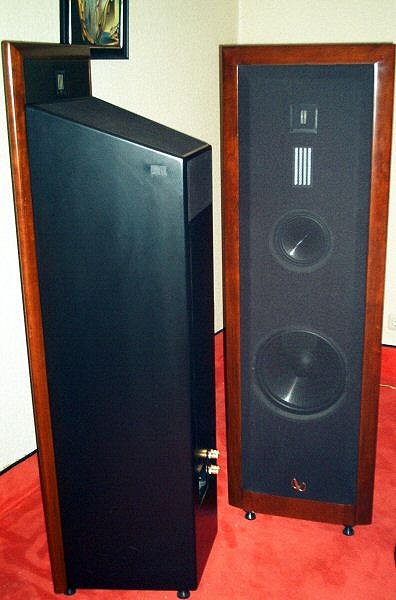
I just stumble upon that IRS Sigma baffles and the implantation with the dipole planar reminded me a bit of the design of the cabinets here :
Infinity Reference Standard Serie
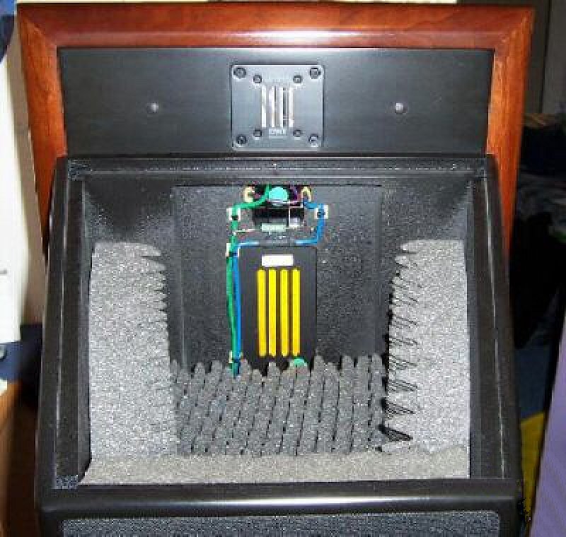
Also is the the design of the front baffle that does not come flush with the back is something that work in general in regards to diffraction ? (I do not mean for the design now but more in general)
Feet recoverd quickly (or mostly so). Unfortunately that meant that my free time was required for that garage redo among other activities (..and I say "redo" now instead of clean-up - because that's what it has become.)

Only a bit like the Infinities.. (the tweeter is open-baffle - which is different, and the midrange "enclosure" isn't quite the same either because it appears as if not only the rear is "open" but the "top" seems to also be open.)
I think they did that for several reasons: aesthetics (panel-look Infinity is known for), reduced reflections for the rear tweeter, reduced resonance for the mid. enclosure (even though it's only a 3-sided "enclosure").
Though a two-chamber (box & tube) "open" design, the Bordeux is much more similar:
It's time for a Bordeaux!
-though I believe they "stuff" the pipe to reduce pip resonances, where I've spec'ed NOT doing that - rather just enough on the walls to minimize resonances.
Note the difference in driver prices vs. yours.
Attachments
Last edited:
Here is preliminary version which is not yet tested in practice (I don't have anything boxed to measure at the moment): VituixCAD_Measurement Preparations_REW.pdf
'Export all measurements..' is probably fastest right after each measurement sequence, though this has separate time window setting + exporting sections copied from ARTA version.

(Skimmed it..) Looks good!
..if I've got *time I'll look to see where things could be improved as far as reader clarity and PM you.
*time is a problem for me right now though,
..but I do something like editing (reader/user clarity) professionally, so there might be a few ideas you'd like to incorporate. Father's day has become Father's month thenFeet recoverd quickly (or mostly so). Unfortunately that meant that my free time was required for that garage redo among other activities (..and I say "redo" now instead of clean-up - because that's what it has become.)
Yes I did noticed the differences, difficult to understand and imagine result of that kind of enclosure as anything coming from the back must be out of phase, does it deliver a kind of sound that is slightly akin to reverb effect ?Only a bit like the Infinities.. (the tweeter is open-baffle - which is different, and the midrange "enclosure" isn't quite the same either because it appears as if not only the rear is "open" but the "top" seems to also be open.)
I think they did that for several reasons: aesthetics (panel-look Infinity is known for), reduced reflections for the rear tweeter, reduced resonance for the mid. enclosure (even though it's only a 3-sided "enclosure").
Though a two-chamber (box & tube) "open" design, the Bordeux is much more similar:
It's time for a Bordeaux!
-though I believe they "stuff" the pipe to reduce pip resonances, where I've spec'ed NOT doing that - rather just enough on the walls to minimize resonances.
That is indeed a lot more look alike!
I don't understand why anyone would use a pipe for mid frequencies as it seem to be one of the worst shape to use if I believe what I have read about diffraction's (standing waves?), stuffed but still.
Here is somebody receiving instruction by Jim Joltz about the stuffing : Boinger's Bordeaux Build - Page 2
I'm impressed with the result of the measurement. Is it smoothed ?
It seem so important to have massive rounded or beveled edges and here two average round-over on each sides and that's it, I quiet don't know what I have to make of that besides the drivers and crossovers would be perfectly adjusted to that shape?!
Note the difference in driver prices vs. yours.
Ho yes thank you for being cheap, but if you advised me those Accutone I would have folded
That leave me money to acquire all the tools I don't have, and I am still far to have all that I need to complete the work on the project
BTW I still can't get my head about your proposition to use that combination of the round-over and bevel bit, that will make an edge on that round-over (and that round bit is shipping for some time now)
Anyway I will have to make that once the cabinet is assembled if not I will not have any support for the router.
[EDIT] Here is what I understand you propose in a sketch :

I was reworking the cabinet a tad in my spare time to accommodate the change from 18mm to 19mm and some minor adjustment, did not reproduce any edge treatment because that is messing with my ability to alter the model, but I will do it once it's final.
It's a design that should age well (like the Bordeaux
)
Last edited:
..back from the abyss, well - momentarily.
I wish I could say most of my free time was spent doing a lot of work.. but it's been watching the World Series of Poker: Main Event. (..it only happens once a year.)
Open-baffle results depend a LOT on how close they are to the "front" wall (and this is relative to freq.). This is also true for open-back designs. They are both doing the same thing - it's just that the open-baffle result is a much wider dispersion for the out-of-phase rear pattern throughout the passband. As you get the speaker closer to that "front" wall (that's presumably reflective) you tend to get a subjective result that is less "precise" (not as easily localized laterally) as far as "direct" (singer/instrument) sound is concerned.
It's time for a Bordeaux!
-both graphs have smoothing, but obviously the 1st one has less smoothing. I personally think the mid.s are elevated more than they should be between about 620 Hz and 1.3 kHz. However, while it generally makes the result more forward, the open-back addition will lower that effect.
You are over-thinking the baffle edges. For a given baffle (within reason), driver placement on baffle is more important and depends on the operating passband.
Your baffle edge representation has the chamfer off-set so it gives top of the baffle more of a narrowed look (toward the top). (..I wouldn't do it like this: just to complicated. Just make a straight support (like a 4x4 board) along the baffle edge with a few clamps on the end and move the router w/ roundover bit along that baffle edge. Repeat for the chamfer.)
Note: I'd use the round-over on the top baffle edge, AND then the chamfer as well. Top edge effects don't show-up a lot with measurements depending on placement, but subjectively (IMO) they are often as disruptive as a lateral/side edge - this is however dependent on the placement of the tweeter relative to the top edge (..and here I'm assuming the tweeter is the closest driver to the top edge of the baffle). It also includes tweeters that are in smaller waveguides (..because effects still tend to react to the near top-edge at the lower end of the driver's passband).
I wish I could say most of my free time was spent doing a lot of work.. but it's been watching the World Series of Poker: Main Event.
(..it only happens once a year.) Open-baffle results depend a LOT on how close they are to the "front" wall (and this is relative to freq.). This is also true for open-back designs. They are both doing the same thing - it's just that the open-baffle result is a much wider dispersion for the out-of-phase rear pattern throughout the passband. As you get the speaker closer to that "front" wall (that's presumably reflective) you tend to get a subjective result that is less "precise" (not as easily localized laterally) as far as "direct" (singer/instrument) sound is concerned.
It's time for a Bordeaux!
-both graphs have smoothing, but obviously the 1st one has less smoothing. I personally think the mid.s are elevated more than they should be between about 620 Hz and 1.3 kHz. However, while it generally makes the result more forward, the open-back addition will lower that effect.
You are over-thinking the baffle edges.
For a given baffle (within reason), driver placement on baffle is more important and depends on the operating passband.Your baffle edge representation has the chamfer off-set so it gives top of the baffle more of a narrowed look (toward the top). (..I wouldn't do it like this: just to complicated. Just make a straight support (like a 4x4 board) along the baffle edge with a few clamps on the end and move the router w/ roundover bit along that baffle edge. Repeat for the chamfer.)
Note: I'd use the round-over on the top baffle edge, AND then the chamfer as well. Top edge effects don't show-up a lot with measurements depending on placement, but subjectively (IMO) they are often as disruptive as a lateral/side edge - this is however dependent on the placement of the tweeter relative to the top edge (..and here I'm assuming the tweeter is the closest driver to the top edge of the baffle). It also includes tweeters that are in smaller waveguides (..because effects still tend to react to the near top-edge at the lower end of the driver's passband).
Last edited:
Hello Scott, Is the alien ship still in there ?..back from the abyss, well - momentarily.
I wish I could say most of my free time was spent doing a lot of work.. but it's been watching the World Series of Poker: Main Event.
So many years I didn't play Poker game, I did with friend and that left me very good memory, cigars, cognac and joy.
Thanks for that explanation, I understand the concept but without actually hearing it and compare to closed design, it's difficult to imagine what is the gain & loss of doing so.Open-baffle results depend a LOT on how close they are to the "front" wall (and this is relative to freq.). This is also true for open-back designs. They are both doing the same thing - it's just that the open-baffle result is a much wider dispersion for the out-of-phase rear pattern throughout the passband. As you get the speaker closer to that "front" wall (that's presumably reflective) you tend to get a subjective result that is less "precise" (not as easily localized laterally) as far as "direct" (singer/instrument) sound is concerned.
It's time for a Bordeaux!
-both graphs have smoothing, but obviously the 1st one has less smoothing. I personally think the mid.s are elevated more than they should be between about 620 Hz and 1.3 kHz. However, while it generally makes the result more forward, the open-back addition will lower that effect.
You are over-thinking the baffle edges.
Your baffle edge representation has the chamfer off-set so it gives top of the baffle more of a narrowed look (toward the top). (..I wouldn't do it like this: just to complicated. Just make a straight support (like a 4x4 board) along the baffle edge with a few clamps on the end and move the router w/ roundover bit along that baffle edge. Repeat for the chamfer.)
Note: I'd use the round-over on the top baffle edge, AND then the chamfer as well. Top edge effects don't show-up a lot with measurements depending on placement, but subjectively (IMO) they are often as disruptive as a lateral/side edge - this is however dependent on the placement of the tweeter relative to the top edge (..and here I'm assuming the tweeter is the closest driver to the top edge of the baffle). It also includes tweeters that are in smaller waveguides (..because effects still tend to react to the near top-edge at the lower end of the driver's passband).
Well, I still can't picture where that chamfer goes
Have you any visual representation of mixing chamfer & roundover ?
My overthinking is a bit linked to your and Kimmosto comments about the importance of chamfer or round-over in diffraction of the frequency responses,
I can see by simulating in VituixCAD that driver placement make the biggest impact in relation to the edges, and that rounding over really play a big role smoothing the response only with a BIG round-over.
Would it be a good experience to build the baffles without any edge treatment, make measurements and then do the round-over after to see the real life differences in the responses?
Though this guy is using a straight bit, same positioning (bearing-guide is on baffle/driver panel):
YouTube
-of course the difference is that he already has his side panels connected and a larger router plate. You won't have side panels, and you don't need a larger plate (though a square plate can be useful in this instance).
So you need to "build-up" the surface for the router to "sit" on (just like the side panel of the subwoofer box shown) that's considerably wider than your baffle's edge/thickness.
Usually you do this with a "L" shaped board that's clamped to the baffle (with the baffle clamped to a work table).
Often you'll enhance that "L" shape with a depth guide for the router's base so that you don't route farther than you should into the side of the baffle.
ex. !L (and ignore the "." on the !): pushing the bottom plate of the router against the ! (minus the ".") which is set to the right depth for the bit (and is reasonably parallel to the baffle edge).
ex. adding the baffle board to that "jig": !L (ignoring the "." on the !) where the underscore under the "L" is the baffle board.
The "jig" should be larger (or at least a fair bit longer than the height of the baffle) so that extends beyond the top and bottom edges of the baffle. It (the portion of the "L" up against the baffle) should also be "deep" enough (extending from the baffle edge toward the other parallel edge of the baffle) so that clamping the jig to the baffle is easy on both (top and bottom of baffle sides).
You can (and should) use the same jig and basic technique for at least the top edge of the baffle.
Last edited:
Yes I have seen that video, but it is indeed just only a chamfer It is the combination of round & chamfer that you proposed that I don't get.
Also in case of chamfer is it not better to start it closer to the driver and make it wider ?
It's just a pass from one end of the baffle edge to the other:
1st with the roundover bit.
2nd with the chamfer bit.
-same depth.
Don't make it to complicated: the easiest method is that ^ ..and honestly, that's better than 90% of builds.
(..a wider chamfer is overall better, but your bit is practically speaking the physical limit.) Of course you could just purchase a 10" table saw and do as shown in the video if you really wanted more.
Last edited:
Though this guy is using a straight bit, same positioning (bearing-guide is on baffle/driver panel):
YouTube
-of course the difference is that he already has his side panels connected and a larger router plate. You won't have side panels, and you don't need a larger plate.
So you need to "build-up" the surface for the router to "sit" on (just like the side panel of the subwoofer box shown) that's considerably wider than your baffle's edge/thickness.
Usually you do this with a "L" shaped board that's clamped to the baffle (with the baffle clamped to a work table).
Often you'll enhance that "L" shape with a depth guide for the router's base so that you don't route farther than you should into the side of the baffle.
ex. !L (and ignore the "." on the !): pushing the bottom plate of the router against the ! (minus the ".") which is set to the right depth for the bit (and is reasonably parallel to the baffle edge).
ex. adding the baffle board to that "jig": !L (ignoring the "." on the !) where the underscore under the "L" is the baffle board.
The "jig" should be larger (or at least a fair bit longer than the height of the baffle) so that extends beyond the top and bottom edges of the baffle. It (the portion of the "L" up against the baffle) should also be "deep" enough (extending from the baffle edge toward the other parallel edge of the baffle) so that clamping the jig to the baffle is easy on both (top and bottom of baffle sides).
You can (and should) use the same jig and basic technique for at least the top edge of the baffle.
Thanks
You are very creative using characters to illustrate board placement, where you doing ASCII pictures for BBS before ?
Yes I think I understand what you say about routing in parallel to the board so the bearing trace against the front baffle
What I planned to do that was to assemble the cabinet and use it as a support, like the guy is doing in the video, that's why also I said that I would have a cabinet without edge treatment that I could measure before I round-over or bevel, isn't that easier than to make a rig for that ?
..I wouldn't do it like that.
I'd specifically do the baffle first - get that 1 kHz up looking good. THEN moving on to the rest of the speaker.
The reasoning here is that you might want to change the baffle shape in some respect to improve the crossover between mid. and tweeter. (..sometimes it's a matter of depth offset between the two drivers - perhaps wanting to inset the tweeter a bit more than the first result and giving yourself "f-up room" in case you make a mistake.)
You don't want to be building box after box before getting a good result.
It's just a pass from one end of the baffle edge to the other:
1st with the roundover bit.
2nd with the chamfer bit.
-same depth.
Don't make it to complicated: the easiest method is that ^ ..and honestly, that's better than 90% of builds.
(..a wider chamfer is overall better, but your bit is practically speaking the physical limit.) Of course you could just purchase a 10" table saw and do as shown in the video if you really wanted more.
Ho ok, but it's basically what I illustrated with the previous sketchup, round over, then bevel that roundover.
Initially I was was going for a simple idea but more information's came and that sent me in a cage ring of thought processes, I am that kind of guy I spend too much time thinking and not enough doing unfortunately.
I have bought a plunge track saw and do not plan a table saw, if need be I could make some rough cuts
You are very creative using characters to illustrate board placement, where you doing ASCII pictures for BBS before ?
It was a cheesy work-around when I found out my browser didn't support sketchup free online.
(..I also looked for router models (to insert) for sketchup and didn't find anything - so it was a bit discouraging overall.)
I have bought a plunge track saw and do not plan a table saw, if need be I could make some rough cuts
FANCY!
I was thinking of something cheap like this:
RYOBI 15 Amp 10 in. Table Saw-RTS10NS - The Home Depot
(..and in fact I'm thinking of one of these for myself just for "ripping" plywood board, though most of the time I get my (few) rip-size cuts at the hardware store. I've got a large compound-slide miter saw for most large cuts - but it doesn't handle long cuts.)
Last edited:
..I wouldn't do it like that.
I'd specifically do the baffle first - get that 1 kHz up looking good. THEN moving on to the rest of the speaker.
The reasoning here is that you might want to change the baffle shape in some respect to improve the crossover between mid. and tweeter. (..sometimes it's a matter of depth offset between the two drivers - perhaps wanting to inset the tweeter a bit more than the first result and giving yourself "f-up room" in case you make a mistake.)
You don't want to be building box after box before getting a good result.
So I may be confused about words, when you say "baffle" do you say front panel of the cabinet ? (in green on the picture below)
If yes then does that mean I would make measurements at first without the actual cabinet but just that front part ?

FANCY!
I was thinking of something cheap like this:
RYOBI 15 Amp 10 in. Table Saw-RTS10NS - The Home Depot
(..and in fact I'm thinking of one of these for myself just for "ripping" plywood board, though most of the time I get my (few) rip-size cuts at the hardware store. I've got a large compound-slide miter saw for most large cuts - but it doesn't handle long cuts.)
Ho nothing fancy I bought a cheap one just to make sure I could cut straight
PARKSIDE(R) Invalzaag met geleiderails PTSS 1200 C | LIDL
That RYOBI is quiet cheap indeed and can do angle cuts, nice when you have a workshop area, one day...
Miter Saw is quiet useful also but I'll stick to a jigsaw for the few cuts I make
- Status
- This old topic is closed. If you want to reopen this topic, contact a moderator using the "Report Post" button.
- Home
- Design & Build
- Software Tools
- Advices on First Crossover Design (VituixCAD2)