Hi ScottG,
Ok thanks I understand what I have to do with the panel, I'll think about if and how I can integrate that in my humble abode
Meanwhile I have continued working on the actual cabinet design :
Added the kind of "UltraTouch" to represent myself the thickness and position, 4cm I don't find so I added the 5cm in place, the 8cm is ok. How to you fixate that thing by the way ?
Modified a bit the stand and added the multi-directional casters
Added bracing, there I swim in trouble waters, no idea if that is ok for the sound but also for the bracing, when I look at that Echelon cabinet bracing's it seem to much to go that far if I consider the different size and type of woofer in the cabinet.
Still no exact idea where I'll place the crossover and binding posts, I guess in a box at the back
I didn't lower the woofer at the moment, I will think about it when I know where I go with the wool panels
Some screenshots :
Meanwhile I have continued working on the actual cabinet design :
You are too far ahead there.
")
What I proposed was a guess - something basic (volume and baffle dimensions) for modeling.
Get good measurements first from your drivers and then start into Vituixcad. If something looks promising there, then (only then) do a mock-up of the midrange and basic "open" enclosure and measure that.
After that you (and you've got a better idea of things), do you start delving into the design with more detail.
-I'm such a killjoy..
Don't worry I know that, it's just that in the meantime I don't have anything else I can do for that project.
I can't order the Fostex or the Gradient because I am soon leaving the country, the only driver I have is the LS plan.
Also I can't start doing the test rig now so I have pretty much only that to play with
I can't order the Fostex or the Gradient because I am soon leaving the country, the only driver I have is the LS plan.
Also I can't start doing the test rig now so I have pretty much only that to play with
I will do that once I get back from Vietnam in April, I'll do something like zaphaudio you linked already, the pictures of the setup are not very good but I get the idea.
Few questions to prepare myself then :
1- Is a board of 47x47inches (122x122cm) OK? Default board size around are 244x122, this if I understand well would allow to measure 283hz at the lowest.
2- what about that very little gap between the insert and the board, do I need to fill it up ?
3- One thing I worry about is destroy the tweeters in the tests, would I have to build a basic high-pass filter for it before testing ? Does it impact measurements ?
4- In Zaphaudio he briefly mention that the bracing type matters a lot but do not describe in detail, what is good or bad practice? Can you point out some other sources ?
I need to flush the drivers in the insert for measurements, so I'll need to get my hands on a routing tool for that also. (not sure I want to so with chisel and mallet)
Then I need to find a way to simply and accurately align the microphone to measure the on & off axis
Finally find a quiet time to do the measurements
Few questions to prepare myself then :
1- Is a board of 47x47inches (122x122cm) OK? Default board size around are 244x122, this if I understand well would allow to measure 283hz at the lowest.
2- what about that very little gap between the insert and the board, do I need to fill it up ?
3- One thing I worry about is destroy the tweeters in the tests, would I have to build a basic high-pass filter for it before testing ? Does it impact measurements ?
4- In Zaphaudio he briefly mention that the bracing type matters a lot but do not describe in detail, what is good or bad practice? Can you point out some other sources ?
I need to flush the drivers in the insert for measurements, so I'll need to get my hands on a routing tool for that also. (not sure I want to so with chisel and mallet
) Then I need to find a way to simply and accurately align the microphone to measure the on & off axis
Finally find a quiet time to do the measurements
-good cabinet building pretty much requires a PLUNGE router (it can be cheap/used or borrowed or rented) and the bit's you require for the cuts, something like a Jasper Jig, clamps (cheap), and guide-board (which is just a dimensionally stable/straight board to work against), and work surface that's long enough. ..err, and a ruler + tape measure + pencil.
1. - it really depends on low freq. you are "shooting" for, it's better to have a larger board.. but it's up to you. I know space is often cramped in Belgium (depending on where you live).. so IF you wanted to do a larger board you could make it "collapsible" that bolts together, perhaps 50 cm square boards with rear frames for the bolts.
2. - Tape or Putty - front only.
3. - Large value cap.
4. - Most people do bracing completely wrong. Don't worry - we'll get to that later. (..it's actually much less complex than what you have shown to get a much better result. I like to add complexity to that with panel-damping, in part for better damping.. but particularly for reduced sound transmission through the cabinet walls. I HATE sound absorption on interior walls for sealed or bass reflex designs - sucks the "life" out of the sound and reduces apparent depth.)
..protractor.
Last edited:
-good cabinet building pretty much requires a PLUNGE router (it can be cheap/used or borrowed or rented) and the bit's you require for the cuts, something like a Jasper Jig, clamps (cheap), and guide-board (which is just a dimensionally stable/straight board to work against), and work surface that's long enough. ..err, and a ruler + tape measure + pencil.
Pencil? What kind of pencil?
(joke)And a circular saw to cut the the panels don't seem a luxury, I don't feel completely useless I got a drill already!
1. - it really depends on low freq. you are "shooting" for, it's better to have a larger board.. but it's up to you. I know space is often cramped in Belgium (depending on where you live).. so IF you wanted to do a larger board you could make it "collapsible" that bolts together, perhaps 50 cm square boards with rear frames for the bolts.
I am not sure I catch what you are meaning by "What frequency I am shooting for" obviously I'd like to make sure the cabinet I make have good low frequencies, so I have to make the measurement as accurate as I can with the constraints I have.
Now tell me if I am wrong but if I succeed to reach a 150cm wide panel I should be good to 200hz (using a wavelength calculator) but do the height matter as much as the width?
After all, the measurements I will be doing are on-axis and off-axis only on a horizontal plane, if not I could do three time 50cm by 122cm and the center piece with a cutout of 40cm to leave 5cm on each side of the cutout.
And the rest of frequencies below 200hz would be merged from a near-field measurement
Well you are right it is pretty cramped in here where I live, this limitation frustrate me but I have to live with it for now.
OK easy fix2. - Tape or Putty - front only.
3. - Large value cap.
Hmm...please define large.
So from what I have read it's a 1st order crossover with a 6db slope, I suppose the value of the capacitor I should use with a tweeter is defined by how low this one can go.
In this case the LS plan.
The specifications sheet say it's a tweeter that is usable from 5khz to 30khz, the suggested crossover is at the lowest a Butterworth 2nd order from 4Khz.
A 20uf Capacitor is going quiet low compared to that 2nd Order, what I don't know is what is the safe frequency and level for that tweeter, I guess it also depend of the level I will have to reach to measure above that noise floor for an accurate measurement.
4. - Most people do bracing completely wrong. Don't worry - we'll get to that later. (..it's actually much less complex than what you have shown to get a much better result. I like to add complexity to that with panel-damping, in part for better damping.. but particularly for reduced sound transmission through the cabinet walls. I HATE sound absorption on interior walls for sealed or bass reflex designs - sucks the "life" out of the sound and reduces apparent depth.)
OK bracings on hold
Damping, yeah 15 years ago when I made a subwoofer sealed box for my car I used some kind of tar paint in thick layer that needed ages to dry and had a foul smell then I filled it with Dacron fibers and some kind of tar sheets in the doors and around the mdf spacers, I spend so much time on that car to make it sound good, in the end I crashed it not a year after, not a big accident just enough to make the car not worth repairs.
When you speak of damping is it something more like that Acoust-X goo ?
Yeah I have my eyes on one with a kind of ruler attached to it..protractor.
Tomorrow I pack my luggage's

BTW nice sales on these : Gradient Axis AXT-12 | Speakers Intertechnik - Shop - Shop
Now tell me if I am wrong but if I succeed to reach a 150cm wide panel I should be good to 200hz (using a wavelength calculator) but do the height matter as much as the width?
After all, the measurements I will be doing are on-axis and off-axis only on a horizontal plane, if not I could do three time 50cm by 122cm and the center piece with a cutout of 40cm to leave 5cm on each side of the cutout.
And the rest of frequencies below 200hz would be merged from a near-field measurement
..it's not exactly a "static" thing.
(Test) Baffle edges induce diffractive ringing depending on distance from the source. ..a 150 cm by 150 cm open panel is good enough down to about 550 Hz, driver centered without any acoustic absorption on the edge and at a distance of 1 meter. You can improve on that with a mineral wool surround (edges of baffle) of sufficient thickness (10 cm) - maybe 300 Hz. As you move closer to the driver, the quality improves a bit lower in freq.
In this respect (a baffle that size testing in that manner), is quite likely to be more of a limit than the room itself (and reflections) - assuming you have the driver away from points of reflection (..like floor and ceiling - say 4 feet from the driver center for each).
A 4 x 8 (foot) sheet is good to almost 400 Hz 1 meter without edge treatment.
Last edited:
Hmm...please define large.
So from what I have read it's a 1st order crossover with a 6db slope, I suppose the value of the capacitor I should use with a tweeter is defined by how low this one can go.
Note: this isn't an absolute requirement (..unless the driver has a small transformer like a ribbon), IF you have your protocol down (no high spl "spikes").
The cap depends on the Impedance of the driver. The lower the impedance, the larger the cap.
-you want a cap that's large enough to have almost no effect on the response you are measuring. It's a DC blocker for the tweeter. Say, 100 uf of cheap non-electrolytic cap for 8 ohms.
ex.
ERSE - PulseX
When you speak of damping is it something more like that Acoust-X goo ?
Nope.
BTW nice sales on these : Gradient Axis AXT-12 | Speakers Intertechnik - Shop - Shop
-it's a nice looking driver, but it's going to require a LOT of volume (for it's lower freq. extension).. and it's not nearly as efficient nor is its mass comparable (for a give surface area).
..it's not exactly a "static" thing.
(Test) Baffle edges induce diffractive ringing depending on distance from the source. ..a 150 cm by 150 cm open panel is good enough down to about 550 Hz, driver centered without any acoustic absorption on the edge and at a distance of 1 meter. You can improve on that with a mineral wool surround (edges of baffle) of sufficient thickness (10 cm) - maybe 300 Hz. As you move closer to the driver, the quality improves a bit lower in freq.
In this respect (a baffle that size testing in that manner), is quite likely to be more of a limit than the room itself (and reflections) - assuming you have the driver away from points of reflection (..like floor and ceiling - say 4 feet from the driver center for each).
A 4 x 8 (foot) sheet is good to almost 400 Hz 1 meter without edge treatment.
Well, in the end I don't really understand the principle behind that setup for the measurement, but that is to be expected.
I have noted by searching online that often I find measurement done with the driver already placed in a cabinet, and the few I see where the measurement is done with a large front panel they don't write much about it.
Article : Speaker baffle design, diffraction and baffle step – Audio Judgement
In the linked article find some things my brain can process, I don't know if it's accurate.
By going with a to measure with a large front panel are we avoiding that the edge diffraction of the higher frequencies and back firing waves "pollute" the measurement ?
I was supposing with any panel size and edge type it was possible to interpret the frequency response and compensate the reading, but from what you write it seem it is not that simple.
The other problem I see if I get what you are writing right is that in practice my drivers will be placed at the center of that +-5x5 that mean it will effectively have the floor +-2.5 feet from center (You ask for 4 feet).
Would it not be possible to play with a front panel that is the size of the actual cabinet project, close the sides of it and use some absorbing material at the back to eliminate some of the back firing waves?
Note: this isn't an absolute requirement (..unless the driver has a small transformer like a ribbon), IF you have your protocol down (no high spl "spikes").
The cap depends on the Impedance of the driver. The lower the impedance, the larger the cap.
-you want a cap that's large enough to have almost no effect on the response you are measuring. It's a DC blocker for the tweeter. Say, 100 uf of cheap non-electrolytic cap for 8 ohms.
ex.
ERSE - PulseX
The part you say "if I respect the protocol" is the one I'm afraid
I have noticed that when I disconnect the USB connection from that UMC204HD interface it send a loud pop in the speakers, scary.
EDIT: I think I will practice my protocol with Boston Acoustics drivers I still have from before (Neo5t, 5.5lf, 6.5lf) and then go with the LS plan when I am familiar with the process
Last edited:
-it's a nice looking driver, but it's going to require a LOT of volume (for it's lower freq. extension).. and it's not nearly as efficient nor is its mass comparable (for a give surface area).
I was not suggesting to replace the AXP-08 but I found them nice for the price.
..it seem it is not that simple.
The other problem I see if I get what you are writing right is that in practice my drivers will be placed at the center of that +-5x5 that mean it will effectively have the floor +-2.5 feet from center (You ask for 4 feet).
Would it not be possible to play with a front panel that is the size of the actual cabinet project, close the sides of it and use some absorbing material at the back to eliminate some of the back firing waves?
It's not that simple.. but it doesn't have to be particularly complicated either.
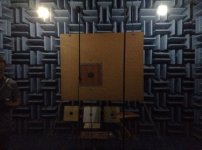
The "IEC" has several baffles for testing. (see the pic. below.)
Just remember that you are mostly interested in freq.s above 1 kHz.. for typical domestic (far-field) measurements.
BUT you want your windowing (reflection free zone) more than an octave below that if possible. (..windowing introduces artifacts to the measurement for an octave plus above it's freq..) So ideally you want your window to be lower than 500 Hz.
Yeah, you need to lift the test baffle off of the floor (stand) and have the driver almost equidistant from floor and ceiling. Alternatively you can stack pillows at the bottom of the floor. Or you could do a ground-plane measurement. (..you'll have to search for that.)
Measuring on a speaker cabinet already assumes the speaker is "the" shape: it takes a huge "chunk" out of the process of loudspeaker design within a modeling program. What happens if that's not the cabinet shape that you want for a really good design? ..or (particularly) the driver isn't placed in exactly the same position you want for a really good design? It's an ***-backwards way to design a loudspeaker.
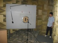
Note: with the off-center position and measuring off-axis: measure off-axis toward the most distant point of the test baffle. Ex. in the pic. with the gentleman off to the right of the test baffle, you would move the mic./mic stand to the left of the board (using a protractor + ruler to get the right angle and distance from the driver being tested). This is for omni sources where you need only one group of angles out to 70 degrees (or so). HOWEVER for your little line tweeter you might want to test it again the same way/mic position but a second time with the tweeter rotated 90 degrees (on the test baffle) so that you measure the vertical response with the same amount of baffle. (..however there should be little practical difference with the measurement so high in freq..)
-btw, nothing says that the baffle need be made of wood. I've done it with small driver-mount area of wood and the rest of it with damped cardboard on a rear frame before.
Attachments
I have noticed that when I disconnect the USB connection from that UMC204HD interface it send a loud pop in the speakers, scary.
..and:
FACE-PALM!


um.. yeah, lets not do that.
Hello Scottg,
Hope all is well for you
I"m back from my trip
It resulted in a pretty big change in my life hopefully that will not slow down too much this project.
I am at the moment thinking about the router model I will purchase, I could settle for a dirt cheap one but at the same time I think I could also use it in the longer term for other wood-work tasks so not decided yet.
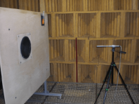
In parallel I am thinking about the design for that test rig, I want to go for total size of horizontal of 8 feets and 6 feets vertical, the main board will be 4'x4' in MDF and the other parts in a lighter rigid material that I didn't found yet (sandwich panel?)
For the inserts it I think I have it right, I will make a square of 13.77 inches with a lip that will be held in place in the back with some toggle clamps, and for small drivers I will make another insert of 4.72 inches into that bigger insert also held with clamps
I started with a basic structure but I quickly realized it was not going to be practical, the design issue I have is to make a structure to hold everything together that is removable and easily stored taking a minimum footprint when not in use.
If you still have time to answer I have a few questions :
1- I have seen on a few pictures of similar test rig that the insert is not in the middle, I suppose it's to evade that square effect in diffraction, should I do that ?
2- Do you know a small amplifier that I could use instead of every time having to unplug my main home one?
3- My noise floor can can reach 50dB, what is the acceptable lower limit dB to measure the with the sweep so that I have enough headroom that the test is not impacted by ambient noise ?
The unfinished rig :


Thanks
Hope all is well for you
I"m back from my trip
It resulted in a pretty big change in my life hopefully that will not slow down too much this project.
I am at the moment thinking about the router model I will purchase, I could settle for a dirt cheap one but at the same time I think I could also use it in the longer term for other wood-work tasks so not decided yet.
In parallel I am thinking about the design for that test rig, I want to go for total size of horizontal of 8 feets and 6 feets vertical, the main board will be 4'x4' in MDF and the other parts in a lighter rigid material that I didn't found yet (sandwich panel?)
For the inserts it I think I have it right, I will make a square of 13.77 inches with a lip that will be held in place in the back with some toggle clamps, and for small drivers I will make another insert of 4.72 inches into that bigger insert also held with clamps
I started with a basic structure but I quickly realized it was not going to be practical, the design issue I have is to make a structure to hold everything together that is removable and easily stored taking a minimum footprint when not in use.
If you still have time to answer I have a few questions :
1- I have seen on a few pictures of similar test rig that the insert is not in the middle, I suppose it's to evade that square effect in diffraction, should I do that ?
2- Do you know a small amplifier that I could use instead of every time having to unplug my main home one?
3- My noise floor can can reach 50dB, what is the acceptable lower limit dB to measure the with the sweep so that I have enough headroom that the test is not impacted by ambient noise ?
The unfinished rig :
Thanks
- Status
- This old topic is closed. If you want to reopen this topic, contact a moderator using the "Report Post" button.
- Home
- Design & Build
- Software Tools
- Advices on First Crossover Design (VituixCAD2)