Hello all,
over XMAS, many guys were celebrating (including the gold bugs though the price is still low), others were drinking, praying or staring at a screen with horrible charts (stock market guys).
I have been staring at an LTSPICE screen for many hours with the final result "time step too small". Need help!
Goals: Self Oscillating Class D SOCD SIC with 7.5KW into 8 Ohms using SICs and 1 x 360V supply (the cooling is another story!!)
4KW into 4 Ohms or 16 Ohms
Whole impedance range of 4 - 16 Ohms with clean step response (fast rise time, almost no overshoot, ...)
The usual 20 Hz - 20 kHz BW, self oscillating, 100% stable under no load and capacitive load.
Not sure if my charge pumped gating concept with slightly negative off state voltage will fly - simulation does not converge.
Quite much for a few days off?
Look at my next post for the current schematic...
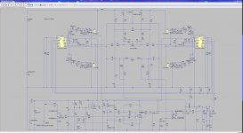
Share the sim file and the driver if you want others to help you out
The sim is running now, since I found and fixed the schematic error! It is SLOW, but I got already a few hundred microseconds.
As expected with that high rail voltage, the switching ripple is still quite high, even at >400kHz.
Why the high rail voltage - no one needs so many KW on one channel, right? Not quite - think about the concept of headroom and dynamics. In order to push maybe a clean 2KW of music power on average, the transients are MUCH higher. You can cut them or convey them cleanly. The power supply and cooling concept does NOT need to support continuous 8KW per channel, and you can still benefit fom that high rail voltage / burst power.
Next posting will be about my ideas for the PSU...
I propose a 3 phase PSU for a 2 channel amp.
Connect the 2 amp channels on one 360V rail and supply the DC bus with 3 independent PSUs, each connected phase-neutral. The PSUs should be connected in parallel directly at the rail, otherwise work independently - so the amp can still work with one or 2 phases missing or on a single phase household line - at reduced power. Don't care too much about light load power sharing - the PSUs would share automatically at high load if one is going into power limit.
Topology for each of the 3 PSUs: Boost PFC -> 400VDC - LLC converter -> 360V rail plus aux rail of 21V. The 5.4V for the comparator can be obtained with a linear regulator from the 21V.
For a two channel amp, I think it would be way enough if the 3 PSUs together can deliver 4500W continuously at the 360V rail. Add a combined overload capability of maybe 10000W for up to one second, while big electrolytics would help to get through shorter bursts of even bigger power and you are good to go.
DIYaudio does not let me upload *.lib files (why?).
Zip them, then will be up loadable.
Just replaced the 4V7 zeners by more appropriate BZX3V6. I 'll upload all the *.lib files in zipped form here. Unfortunetely, the LTSPICE does not "like" the BZX3V6, so it is all convergence errors again.
@kASD: You using something like the RECOM R12P22005D, right?
@kASD: You using something like the RECOM R12P22005D, right?
Attachments
Unfortunetely, the LTSPICE does not "like" the BZX3V6
"
********************************
* Copyright: *
* Vishay Intertechnology, Inc. *
********************************
BZX55C3V6
"
Put "*" before "BZX55C3V6".
Back to 4V7 zener. the negative gate voltage will be a bit high comapred to ROHM's -4V abs max rating. Not sure if that low rating is real.
Noticed some subharmonic oscillation tendency at high excursion. Reason is the comparator does not switch in time if too low overdrive is present. In contrast to the usual gradual frequency drop as the voltage approaches rails, here the frequency will suddenly jump to half. The solution is to increase the impedance of RC between the inputs of the main comparator, hence to increase it's overdrive, at the expense of loop gain.
Noticed some subharmonic oscillation tendency at high excursion. Reason is the comparator does not switch in time if too low overdrive is present. In contrast to the usual gradual frequency drop as the voltage approaches rails, here the frequency will suddenly jump to half. The solution is to increase the impedance of RC between the inputs of the main comparator, hence to increase it's overdrive, at the expense of loop gain.
- Status
- This old topic is closed. If you want to reopen this topic, contact a moderator using the "Report Post" button.
- Home
- Design & Build
- Software Tools
- XMAS work: LTSPICE SOCD SIC - "time step too small"