The subharmonic pulse-skipping seems to be persistent when the voltage approaches the rails even if I significantly increase the RC impedance. Not sure if a few volts of 210kHz ripple or even 137kHz is any real world problem when the output power is several KW. Honestly, I do not think so... but some high end audio guys may not like this....hhmmm
I use my own floating isolated supply based on toroidal ferrite core which gives less than 5pF isolation capacitance between secondary and primary. Both Hi & LO sides are powered this way. This way the reliability goes up and things get simple to tune like one can adjust the real time dead-time, gate driver charging rate of both sides without even connecting the main rail voltage bus. You just have to feed the gate driver with a square wave signal of your choice to reveal the outcome at the mosfet gates in order to fine tune the drives. This is how industrial motor inverter gate drives are configured using IGBTs.
With bootstrap option there is a considerable difference in amplitude of both gate drives [HI side is always less than LO side amplitude in real world conditions acquainting the fact that the charging of Hi side capacitor happens thru LO side Mosfet and its RDS based voltage drop causes the gate drive to get lessen by couple of volts or so, when it is conducting several amperes of current in real world applications, which leads to uneven heating of mosfets], which is not the case here. You get same amplitude gate drives,which means symmetric rise and fall times at switching output node during dynamic behaviour and No fear of 0 or 100% modulation time interval causing boot capacitor charge failure.
Btw-Shift your thread under Class-D section for better response.
Attachments
Last edited:
@kASD: I know the advantages of floating supply. But the disadvantage is added cost / complexity. So my idea was to "get away" with charge pumping. My sims show that it more or less is working. I ll post my current sim file soon when I am done for today (and done for this year 2018).
Funny thing is, that I started that thread in Class D section, but some guy just moved it to here!!
BTW: I am currently working for a company that is doing industrial motor inverter drives using IGBTs..
Funny thing is, that I started that thread in Class D section, but some guy just moved it to here!!
BTW: I am currently working for a company that is doing industrial motor inverter drives using IGBTs..
So the only way to get a working 3V6 zener in LTSPICE was to take the standard.dio, copy the 1N750 model into a new line, change the name to 1N747 and the parameter from 4V7 to 3V6. Saved the new standard.dio and - Working!
The gate voltages start to look somehow "useful" - I m having progress!
The gate voltages start to look somehow "useful" - I m having progress!
Pulse skipping will save switching losses during high power transients.
It is not a bad thing, since:
1. No one can hear any sound above 30kHz, not at all if it is masked by a few kilowatts of audible sound output.
2. The overall RMS power for the voice coil does not increase in any meaningful way.
3. Pulse skipping will not happen at idle with almost no signal.
Anyway, attached you can find the current 2018's final status of SOCD SIC.
(As you can see I have a 4K desktop, an I ll never go back to anything less)
Attachments
Last post for 2018 (I promise, as long as there is nobody talking back or asking!).
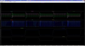
->Topic: Square wave step response. I fed a 2KHz signal to the amp with a steepness way beyond ANY audio signal bandwidth (2us rise and 2us fall time).
Attached the result: 6500W RMS power into 8 Ohms with no ringing and (almost) no overshoot!!
Happy New Year 2019!!
->Topic: Square wave step response. I fed a 2KHz signal to the amp with a steepness way beyond ANY audio signal bandwidth (2us rise and 2us fall time).
Attached the result: 6500W RMS power into 8 Ohms with no ringing and (almost) no overshoot!!
Happy New Year 2019!!
Attachments
Hi Kanwar, if you don't mind, how high frequencies have you managed to push with your gate drive pulse transformer driver and at what rails voltages?
Agreed it's a reliable topology, in the past have worked with motor inverters using 6-pack IGBT's and generally the frequency is lower than what is seen for class D amps, plenty of readily available pulse transformers on the market to explore but the bulk may be tailored mostly for the frequencies seen typical for inverters so one may end up doing ones own gate drive transformer.
Regards and Happy New Year!
Hi Kanwar, if you don't mind, how high frequencies have you managed to push with your gate drive pulse transformer driver and at what rails voltages?
Agreed it's a reliable topology, in the past have worked with motor inverters using 6-pack IGBT's and generally the frequency is lower than what is seen for class D amps, plenty of readily available pulse transformers on the market to explore but the bulk may be tailored mostly for the frequencies seen typical for inverters so one may end up doing ones own gate drive transformer.
Regards and Happy New Year!
Hi Michael,
Happy new year
")
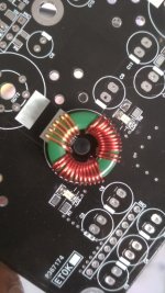
I use the transformer at 500khz with fixed dutycycle of 50%, just to power the gate driver chip at high and low sides at 15VDC. It doesn't serve as the gate driver directly. It's role is of isolated DC-DC converter only.
The rail voltages in half bridge range from +250/-250VDC and some times in a full bridge upto 400VDC.
I am in love with these small transformers,they do wonders whether it's a gate driver supply or powering an isolated current sensor they keep the system ultra reliable and very simple.
Regards
Kanwar
Last edited:
For a two channel amp, I think it would be way enough if the 3 PSUs together can deliver 4500W continuously at the 360V rail. Add a combined overload capability of maybe 10000W for up to one second, while big electrolytics would help to get through shorter bursts of even bigger power and you are good to go.
The new Powersoft X series X4/X8 uses active clamped flyback single stage PFC on each phase,they can run on three and single phase thru parallel combination,has burst capability of 15kW but continuous average is 2kw only. Capacitors are only at secondary side.
Did you all see the fireworks and celebrations around the globe last night?
Well, the reason to celebrate was wedding day between SOCD and SIC:
SOCD: A new Self oscillating class D amp was invented - no need to infringe on UCD patent.
SIC: A new technology that enables 600V parts with fast usable body diode (unlike superjunction) and low Rdson.
SOCD SIC: A revolutionary new multi-KW amplifier that will turn the whole world into one big partyland!!!! Let's get the party started!
@kASD: I can see clearly the need to have the COMP inputs within specified limits, otherwise the COMP may misbehave. In case of my COMP it is -0.1V <-> VCC-1.2V. So why not just use zeners to keep the inputs where they need to be? No need for a common mode correction.....
I use the transformer at 500khz with fixed dutycycle of 50%, just to power the gate driver chip at high and low sides at 15VDC.
ah.. I see, now that's some extreme fidelity supply running such high frequencies.
- Status
- This old topic is closed. If you want to reopen this topic, contact a moderator using the "Report Post" button.
- Home
- Design & Build
- Software Tools
- XMAS work: LTSPICE SOCD SIC - "time step too small"